1. Innføring
Configuration moves from theory to device — HAL device that is. For those who have had just a bit of computer programming, this section is the Hello World of the HAL.
halrun can be used to create a working system. It is a command line or text file tool for configuration and tuning. The following examples illustrate its setup and operation.
2. Halcmd
halcmd is a command line tool for manipulating HAL. A more complete man page exists for halcmd and installed together with LinuxCNC, from source or from a package. If LinuxCNC has been compiled as run-in-place, the man page is not installed but is accessible in the LinuxCNC main directory with the following command:
$ man -M docs/man halcmd2.1. Notation
For this tutorial, commands for the operating system are typically shown without the prompt provided by the UNIX shell, i.e typically a dollar sign ($) or a hash/double cross (#). When communicating directly with the HAL through halcmd or halrun, the prompts are shown in the examples. The terminal window is in Applications/Accessories from the main Ubuntu menu bar.
me@computer:~linuxcnc$ halrun
(vil vises som påfølgende linje)
halrun

(the halcmd: prompt will be shown when running HAL)
halcmd: loadrt counter
halcmd: show pin
2.2. Tab-completion
Your version of halcmd may include tab-completion. Instead of completing file names as a shell does, it completes commands with HAL identifiers. You will have to type enough letters for a unique match. Try pressing tab after starting a HAL command:
halcmd: loa<TAB>
halcmd: load
halcmd: loadrt
halcmd: loadrt cou<TAB>
halcmd: loadrt counter
2.3. The RTAPI environment
RTAPI stands for Real Time Application Programming Interface. Many HAL components work in realtime, and all HAL components store data in shared memory so realtime components can access it. Regular Linux does not support realtime programming or the type of shared memory that HAL needs. Fortunately, there are realtime operating systems (RTOS’s) that provide the necessary extensions to Linux. Unfortunately, each RTOS does things a little differently.
To address these differences, the LinuxCNC team came up with RTAPI, which provides a consistent way for programs to talk to the RTOS. If you are a programmer who wants to work on the internals of LinuxCNC, you may want to study linuxcnc/src/rtapi/rtapi.h to understand the API. But if you are a normal person, all you need to know about RTAPI is that it (and the RTOS) needs to be loaded into the memory of your computer before you do anything with HAL.
3. A Simple Example
3.1. Loading a component
For this tutorial, we are going to assume that you have successfully installed the Live CD and, if using a RIP
[Run In Place, when the source files have been downloaded to a user directory and are compiled and executed directly from there.]
, invoke the rip-environment script to prepare your shell. In that case, all you need to do is load the required RTOS and RTAPI modules into memory. Just run the following command from a terminal window:
cd linuxcnc
halrun
halcmd:
With the realtime OS and RTAPI loaded, we can move into the first example. Notice that the prompt is now shown as halcmd:. This is because subsequent commands will be interpreted as HAL commands, not shell commands.
For the first example, we will use a HAL component called siggen, which is a simple signal generator. A complete description of the siggen component can be found in the SigGen section of this Manual. It is a realtime component. To load the "siggen" component, use the HAL command loadrt.
halcmd: loadrt siggen3.2. Examining the HAL
Now that the module is loaded, it is time to introduce halcmd, the command line tool used to configure the HAL. This tutorial will introduce only a selection of halcmd features. For a more complete description try man halcmd, or see the reference in HAL Commands section of this document. The first halcmd feature is the show command. This command displays information about the current state of the HAL. To show all installed components:
halrun/halcmdhalcmd: show comp
Loaded HAL Components:
ID Type Name PID State
3 RT siggen ready
2 User halcmd2177 2177 readySince halcmd itself is also a HAL component, it will always show up in the list. The number after "halcmd" in the component list is the UNIX process ID. It is possible to run more than one copy of halcmd at the same time (in different terminal windows for example), so the PID is added to the end of the name to make it unique. The list also shows the siggen component that we installed in the previous step. The RT under Type indicates that siggen is a realtime component. The User under Type indicates it is a non-realtime component.
Next, let’s see what pins siggen makes available:
halcmd: show pin

Component Pins:
Owner   Type   Dir        Value  Name
     3  float  IN             1  siggen.0.amplitude
     3  bit    OUT        FALSE  siggen.0.clock
     3  float  OUT            0  siggen.0.cosine
     3  float  IN             1  siggen.0.frequency
     3  float  IN             0  siggen.0.offset
     3  float  OUT            0  siggen.0.sawtooth
     3  float  OUT            0  siggen.0.sine
     3  float  OUT            0  siggen.0.square
     3  float  OUT            0  siggen.0.triangle
This command displays all of the pins in the current HAL. A complex system could have dozens or hundreds of pins. But right now there are only nine pins. Of these pins eight are floating point and one is bit (boolean). Six carry data out of the siggen component and three are used to transfer settings into the component. Since we have not yet executed the code contained within the component, some the pins have a value of zero.
The next step is to look at parameters:
halcmd: show param

Parameters:
Owner   Type  Dir        Value   Name
     3  s32   RO             0   siggen.0.update.time
     3  s32   RW             0   siggen.0.update.tmax
The show param command shows all the parameters in the HAL. Right now, each parameter has the default value it was given when the component was loaded. Note the column labeled Dir. The parameters labeled -W are writable ones that are never changed by the component itself, instead they are meant to be changed by the user to control the component. We will see how to do this later. Parameters labeled R- are read only parameters. They can be changed only by the component. Finally, parameter labeled RW are read-write parameters. That means that they are changed by the component, but can also be changed by the user. Note: The parameters siggen.0.update.time and siggen.0.update.tmax are for debugging purposes and won’t be covered in this section.
Most realtime components export one or more functions to actually run the realtime code they contain. Let’s see what function(s) siggen exported:
halcmd`halcmd: show funct
Exported Functions:
Owner CodeAddr Arg FP Users Name
00003 f801b000 fae820b8 YES 0 siggen.0.updateThe siggen component exported a single function. It is not currently linked to any threads, so users is zero
[CodeAddr and Arg fields were used during development and should probably disappear.]
.
3.3. Making realtime code run
To actually run the code contained in the function siggen.0.update, we need a realtime thread. The component called threads that is used to create a new thread. Lets create a thread called "test-thread" with a period of 1 ms (1,000 µs or 1,000,000 ns):
halcmd: loadrt threads name1=test-thread period1=1000000Let’s see if that worked:
halcmd: show thread

Realtime Threads:
     Period  FP     Name               (     Time, Max-Time )
     999855  YES    test-thread        (        0,        0 )
It did. The period is not exactly 1,000,000 ns because of hardware limitations, but we have a thread that runs at approximately the correct rate. The next step is to connect the function to the thread:
halcmd: addf siggen.0.update test-threadUp till now, we’ve been using halcmd only to look at the HAL. However, this time we used the addf (add function) command to actually change something in the HAL. We told halcmd to add the function siggen.0.update to the thread test-thread, and if we look at the thread list again, we see that it succeeded:
halcmd: show thread

Realtime Threads:
     Period  FP     Name                (     Time, Max-Time )
     999855  YES    test-thread         (        0,        0 )
                  1 siggen.0.update
There is one more step needed before the siggen component starts generating signals. When the HAL is first started, the thread(s) are not actually running. This is to allow you to completely configure the system before the realtime code starts. Once you are happy with the configuration, you can start the realtime code like this:
halcmd: startNow the signal generator is running. Let’s look at its output pins:
halcmd: show pin

Component Pins:
Owner   Type  Dir         Value  Name
     3  float IN              1  siggen.0.amplitude
     3  bit   OUT         FALSE  siggen.0.clock
     3  float OUT    -0.1640929  siggen.0.cosine
     3  float IN              1  siggen.0.frequency
     3  float IN              0  siggen.0.offset
     3  float OUT    -0.4475303  siggen.0.sawtooth
     3  float OUT     0.9864449  siggen.0.sine
     3  float OUT            -1  siggen.0.square
     3  float OUT    -0.1049393  siggen.0.triangle
And let’s look again:
halcmd: show pin

Component Pins:
Owner   Type  Dir         Value  Name
     3  float IN              1  siggen.0.amplitude
     3  bit   OUT         FALSE  siggen.0.clock
     3  float OUT     0.0507619  siggen.0.cosine
     3  float IN              1  siggen.0.frequency
     3  float IN              0  siggen.0.offset
     3  float OUT     -0.516165  siggen.0.sawtooth
     3  float OUT     0.9987108  siggen.0.sine
     3  float OUT            -1  siggen.0.square
     3  float OUT    0.03232994  siggen.0.triangle
We did two show pin commands in quick succession, and you can see that the outputs are no longer zero. The sine, cosine, sawtooth, and triangle outputs are changing constantly. The square output is also working, however it simply switches from +1.0 to -1.0 every cycle.
3.4. Changing Parameters
The real power of HAL is that you can change things. For example, we can use the setp command to set the value of a parameter. Let’s change the amplitude of the signal generator from 1.0 to 5.0:
halcmd: setp siggen.0.amplitude 5halcmd: show param
Parameters:
Owner Type Dir Value Name
3 s32 RO 1754 siggen.0.update.time
3 s32 RW 16997 siggen.0.update.tmax
halcmd: show pin
Component Pins:
Owner Type Dir Value Name
3 float IN 5 siggen.0.amplitude
3 bit OUT FALSE siggen.0.clock
3 float OUT 0.8515425 siggen.0.cosine
3 float IN 1 siggen.0.frequency
3 float IN 0 siggen.0.offset
3 float OUT 2.772382 siggen.0.sawtooth
3 float OUT -4.926954 siggen.0.sine
3 float OUT 5 siggen.0.square
3 float OUT 0.544764 siggen.0.triangleNote that the value of parameter siggen.0.amplitude has changed to 5, and that the pins now have larger values.
3.5. Saving the HAL configuration
Most of what we have done with halcmd so far has simply been viewing things with the show command. However two of the commands actually changed things. As we design more complex systems with HAL, we will use many commands to configure things just the way we want them. HAL has the memory of an elephant, and will retain that configuration until we shut it down. But what about next time? We don’t want to manually enter a bunch of commands every time we want to use the system.
halcmd: save

# components
loadrt threads name1=test-thread period1=1000000
loadrt siggen
# pin aliases
# signals
# nets
# parameter values
setp siggen.0.update.tmax 14687
# realtime thread/function links
addf siggen.0.update test-thread
The output of the save command is a sequence of HAL commands. If you start with an empty HAL and run all these commands, you will get the configuration that existed when the save command was issued. To save these commands for later use, we simply redirect the output to a file:
halcmdhalcmd: save all saved.hal3.6. Exiting halrun
When you’re finished with your HAL session type exit at the "halcmd:" prompt. This will return you to the system prompt and close down the HAL session. Do not simply close the terminal window without shutting down the HAL session.
halcmd: exit3.7. Restoring the HAL configuration
To restore the HAL configuration stored in the file "saved.hal", we need to execute all of those HAL commands. To do that, we use "-f _<file name>_" which reads commands from a file, and "-I" (upper case i) which shows the halcmd prompt after executing the commands:
halrun -I -f saved.halNotice that there is not a "start" command in saved.hal. It’s necessary to issue it again (or edit the file saved.hal to add it there).
3.8. Removing HAL from memory
If an unexpected shutdown of a HAL session occurs you might have to unload HAL before another session can begin. To do this type the following command in a terminal window.
halrun -U4. Stepgen Example
Up till now we have only loaded one HAL component. But the whole idea behind the HAL is to allow you to load and connect a number of simple components to make up a complex system. The next example will use two components.
Before we can begin building this new example, we want to start with a clean slate. If you just finished one of the previous examples, we need to remove the all components and reload the RTAPI and HAL libraries.
halcmd: exit4.1. Installing the components
Now we are going to load the step pulse generator component. For a detailed description of this component refer to the stepgen section of the Integrator Manual. In this example we will use the velocity control type of StepGen. For now, we can skip the details, and just run the following commands.
In this example we will use the velocity control type from the stepgen component.
halrun
halcmd: loadrt stepgen step_type=0,0 ctrl_type=v,v
halcmd: loadrt siggen
halcmd: loadrt threads name1=fast period1=50000 name2=slow period2=1000000
The first command loads two step generators, both configured to generate stepping type 0. The second command loads our old friend siggen, and the third one creates two threads, a fast one with a period of 50 microseconds (µs) and a slow one with a period of 1 millisecond (ms).
The fp1= parameter is deprecated and ignored. All threads now unconditionally support floating point. |
As before, we can use halcmd show to take a look at the HAL. This time we have a lot more pins and parameters than before:
halcmd: show pin

Component Pins:
Owner   Type  Dir         Value  Name
     4  float IN              1  siggen.0.amplitude
     4  bit   OUT         FALSE  siggen.0.clock
     4  float OUT             0  siggen.0.cosine
     4  float IN              1  siggen.0.frequency
     4  float IN              0  siggen.0.offset
     4  float OUT             0  siggen.0.sawtooth
     4  float OUT             0  siggen.0.sine
     4  float OUT             0  siggen.0.square
     4  float OUT             0  siggen.0.triangle
     3  s32   OUT             0  stepgen.0.counts
     3  bit   OUT         FALSE  stepgen.0.dir
     3  bit   IN          FALSE  stepgen.0.enable
     3  float OUT             0  stepgen.0.position-fb
     3  bit   OUT         FALSE  stepgen.0.step
     3  float IN              0  stepgen.0.velocity-cmd
     3  s32   OUT             0  stepgen.1.counts
     3  bit   OUT         FALSE  stepgen.1.dir
     3  bit   IN          FALSE  stepgen.1.enable
     3  float OUT             0  stepgen.1.position-fb
     3  bit   OUT         FALSE  stepgen.1.step
     3  float IN              0  stepgen.1.velocity-cmd

halcmd: show param

Parameters:
Owner   Type  Dir         Value  Name
     4  s32   RO              0  siggen.0.update.time
     4  s32   RW              0  siggen.0.update.tmax
     3  u32   RW     0x00000001  stepgen.0.dirhold
     3  u32   RW     0x00000001  stepgen.0.dirsetup
     3  float RO              0  stepgen.0.frequency
     3  float RW              0  stepgen.0.maxaccel
     3  float RW              0  stepgen.0.maxvel
     3  float RW              1  stepgen.0.position-scale
     3  s32   RO              0  stepgen.0.rawcounts
     3  u32   RW     0x00000001  stepgen.0.steplen
     3  u32   RW     0x00000001  stepgen.0.stepspace
     3  u32   RW     0x00000001  stepgen.1.dirhold
     3  u32   RW     0x00000001  stepgen.1.dirsetup
     3  float RO              0  stepgen.1.frequency
     3  float RW              0  stepgen.1.maxaccel
     3  float RW              0  stepgen.1.maxvel
     3  float RW              1  stepgen.1.position-scale
     3  s32   RO              0  stepgen.1.rawcounts
     3  u32   RW     0x00000001  stepgen.1.steplen
     3  u32   RW     0x00000001  stepgen.1.stepspace
     3  s32   RO              0  stepgen.capture-position.time
     3  s32   RW              0  stepgen.capture-position.tmax
     3  s32   RO              0  stepgen.make-pulses.time
     3  s32   RW              0  stepgen.make-pulses.tmax
     3  s32   RO              0  stepgen.update-freq.time
     3  s32   RW              0  stepgen.update-freq.tmax
4.2. Connecting pins with signals
What we have is two step pulse generators, and a signal generator. Now it is time to create some HAL signals to connect the two components. We are going to pretend that the two step pulse generators are driving the X and Y axis of a machine. We want to move the table in circles. To do this, we will send a cosine signal to the X axis, and a sine signal to the Y axis. The siggen module creates the sine and cosine, but we need wires to connect the modules together. In the HAL, wires are called signals. We need to create two of them. We can call them anything we want, for this example they will be X-vel and Y-vel. The signal X-vel is intended to run from the cosine output of the signal generator to the velocity input of the first step pulse generator. The first step is to connect the signal to the signal generator output. To connect a signal to a pin we use the net command.
halcmd: net X-vel <= siggen.0.cosineTo see the effect of the net command, we show the signals again.
halcmd: show sig

Signals:
Type          Value  Name     (linked to)
float             0  X-vel <== siggen.0.cosine
When a signal is connected to one or more pins, the show command lists the pins immediately following the signal name. The arrow shows the direction of data flow - in this case, data flows from pin siggen.0.cosine to signal X-vel. Now let’s connect the X-vel to the velocity input of a step pulse generator.
halcmd: net X-vel => stepgen.0.velocity-cmdWe can also connect up the Y axis signal Y-vel. It is intended to run from the sine output of the signal generator to the input of the second step pulse generator. The following command accomplishes in one line what two net commands accomplished for X-vel.
halcmd: net Y-vel siggen.0.sine => stepgen.1.velocity-cmdNow let’s take a final look at the signals and the pins connected to them.
halcmd: show sig

Signals:
Type          Value  Name     (linked to)
float             0  X-vel <== siggen.0.cosine
                           ==> stepgen.0.velocity-cmd
float             0  Y-vel <== siggen.0.sine
                           ==> stepgen.1.velocity-cmd
The show sig command makes it clear exactly how data flows through the HAL. For example, the X-vel signal comes from pin siggen.0.cosine, and goes to pin stepgen.0.velocity-cmd.
4.3. Setting up realtime execution - threads and functions
Thinking about data flowing through "wires" makes pins and signals fairly easy to understand. Threads and functions are a little more difficult. Functions contain the computer instructions that actually get things done. Thread are the method used to make those instructions run when they are needed. First let’s look at the functions available to us.
halcmd: show funct

Exported Functions:
Owner   CodeAddr  Arg       FP   Users  Name
 00004  f9992000  fc731278  YES      0   siggen.0.update
 00003  f998b20f  fc7310b8  YES      0   stepgen.capture-position
 00003  f998b000  fc7310b8  NO       0   stepgen.make-pulses
 00003  f998b307  fc7310b8  YES      0   stepgen.update-freq
In general, you will have to refer to the documentation for each component to see what its functions do. In this case, the function siggen.0.update is used to update the outputs of the signal generator. Every time it is executed, it calculates the values of the sine, cosine, triangle, and square outputs. To make smooth signals, it needs to run at specific intervals.
The other three functions are related to the step pulse generators.
The first one, stepgen.capture_position, is used for position feedback. It captures the value of an internal counter that counts the step pulses as they are generated. Assuming no missed steps, this counter indicates the position of the motor.
The main function for the step pulse generator is stepgen.make_pulses. Every time make_pulses runs it decides if it is time to take a step, and if so sets the outputs accordingly. For smooth step pulses, it should run as frequently as possible. Because it needs to run so fast, make_pulses is highly optimized and performs only a few calculations.
The last function, stepgen.update-freq, is responsible for doing scaling and some other calculations that need to be performed only when the frequency command changes.
What this means for our example is that we want to run siggen.0.update at a moderate rate to calculate the sine and cosine values. Immediately after we run siggen.0.update, we want to run stepgen.update_freq to load the new values into the step pulse generator. Finally we need to run stepgen.make_pulses as fast as possible for smooth pulses. Because we don’t use position feedback, we don’t need to run stepgen.capture_position at all.
We run functions by adding them to threads. Each thread runs at a specific rate. Let’s see what threads we have available.
halcmd: show thread

Realtime Threads:
     Period  FP     Name               (     Time, Max-Time )
     996980  YES                  slow (        0,        0 )
      49849  YES                  fast (        0,        0 )
The two threads were created when we loaded threads. The first one, slow, runs every millisecond. We will use it for siggen.0.update and stepgen.update_freq. The second thread is fast, which runs every 50 microseconds (µs). We will use it for stepgen.make_pulses. To connect the functions to the proper thread, we use the addf command. We specify the function first, followed by the thread.
halcmd: addf siggen.0.update slow
halcmd: addf stepgen.update-freq slow
halcmd: addf stepgen.make-pulses fast
After we give these commands, we can run the show thread command again to see what happened.
halcmd: show thread

Realtime Threads:
     Period  FP     Name               (     Time, Max-Time )
     996980  YES                  slow (        0,        0 )
                  1 siggen.0.update
                  2 stepgen.update-freq
      49849  NO                   fast (        0,        0 )
                  1 stepgen.make-pulses
Now each thread is followed by the names of the functions, in the order in which the functions will run.
4.4. Setting parameters
We are almost ready to start our HAL system. However we still need to adjust a few parameters. By default, the siggen component generates signals that swing from +1 to -1. For our example that is fine, we want the table speed to vary from +1 to -1 inches per second. However the scaling of the step pulse generator isn’t quite right. By default, it generates an output frequency of 1 step per second with an input of 1.0. It is unlikely that one step per second will give us one inch per second of table movement. Let’s assume instead that we have a 5 turn per inch leadscrew, connected to a 200 step per rev stepper with 10x microstepping. So it takes 2000 steps for one revolution of the screw, and 5 revolutions to travel one inch. That means the overall scaling is 10000 steps per inch. We need to multiply the velocity input to the step pulse generator by 10000 to get the proper output. That is exactly what the parameter stepgen.n.velocity-scale is for. In this case, both the X and Y axis have the same scaling, so we set the scaling parameters for both to 10000.
halcmd: setp stepgen.0.position-scale 10000
halcmd: setp stepgen.1.position-scale 10000
halcmd: setp stepgen.0.enable 1
halcmd: setp stepgen.1.enable 1
This velocity scaling means that when the pin stepgen.0.velocity-cmd is 1.0, the step generator will generate 10000 pulses per second (10 kHz). With the motor and leadscrew described above, that will result in the axis moving at exactly 1.0 inches per second. This illustrates a key HAL concept - things like scaling are done at the lowest possible level, in this case in the step pulse generator. The internal signal X-vel is the velocity of the table in inches per second, and other components such as siggen don’t know (or care) about the scaling at all. If we changed the leadscrew, or motor, we would change only the scaling parameter of the step pulse generator.
4.5. Run it!
We now have everything configured and are ready to start it up. Just like in the first example, we use the start command.
halcmd: startAlthough nothing appears to happen, inside the computer the step pulse generator is cranking out step pulses, varying from 10 kHz forward to 10 kHz reverse and back again every second. Later in this tutorial we’ll see how to bring those internal signals out to run motors in the real world, but first we want to look at them and see what is happening.
5. Halmeter
You can build very complex HAL systems without ever using a graphical interface. However there is something satisfying about seeing the result of your work. The first and simplest GUI tool for the HAL is halmeter. It is a very simple program that is the HAL equivalent of the handy multimeter (or analog meter for the old timers).
It allows to observe the pins, signals or parameters by displaying the current value of these entities. It is very easy to use application for graphical environments. In a console type:
halmeterTwo windows will appear. The selection window is the largest and includes three tabs:
-
One lists all the pins currently defined in HAL,
-
one lists all the signals,
-
one lists all the parameters.
Click on a tab, then click on one of the items to select it. The small window will show the name and value of the selected item. The display is updated approximately 10 times per second. To free screen space, the selection window can be closed with the Close button. On the little window, hidden under the selection window at program launch, the Select button, re-opens the selection window and the Exit button stops the program and closes both windows.
It is possible to run several halmeters simultaneously, which makes it possible to visualize several items at the same time. To open a halmeter and release the console by running it in the background, run the following command:
halmeter &It is possible to launch halmeter and make it immediately display an item. For this, add pin|sig|par[am] name arguments on the command line. It will display the signal, pin, or parameter name as soon as it will start. If the indicated item does not exist, it will start normally.
Finally, if an item is specified for display, it is possible add -s in front of pin|sig|param to tell halmeter to use an even smaller window. The item name will be displayed in the title bar instead of below the value and there will be no button. This is useful for displaying a lot of halmeters in a small space.
We will use the siggen component again to check out halmeter. If you just finished the previous example, then you can load siggen using the saved file. If not, we can load it just like we did before:
halrun
halcmd: loadrt siggen
halcmd: loadrt threads name1=test-thread period1=1000000
halcmd: addf siggen.0.update test-thread
halcmd: start
halcmd: setp siggen.0.amplitude 5
At this point we have the siggen component loaded and running. It’s time to start halmeter.
halcmd: loadusr halmeterThe first window you will see is the "Select Item to Probe" window.
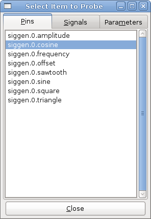
This dialog has three tabs. The first tab displays all of the HAL pins in the system. The second one displays all the signals, and the third displays all the parameters. We would like to look at the pin siggen.0.cosine first, so click on it then click the "Close" button. The probe selection dialog will close, and the meter looks something like the following figure.
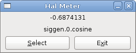
To change what the meter displays press the "Select" button which brings back the "Select Item to Probe" window.
You should see the value changing as siggen generates its cosine wave. Halmeter refreshes its display about 5 times per second.
To shut down halmeter, just click the exit button.
If you want to look at more than one pin, signal, or parameter at a time, you can just start more halmeters. The halmeter window was intentionally made very small so you could have a lot of them on the screen at once.
6. Halshow
The script halshow can help you find your way around a running HAL. It displays chosen HAL values and updates them continuously.
This is a very specialized system and it must connect to a working HAL. It cannot run standalone because it relies on the ability of HAL to "introspect" and report what it knows of itself through the halcmd interface library. When the configuration of LinuxCNC changes, so will the output of halshow be different, too.
As we will soon see, this ability of HAL to document itself is one key to establish an effective CNC system.
6.1. Starting Halshow
Halshow is available
-
in the AXIS menu under Machine/Show HAL Configuration,
-
in the TkLinuxCNC menu under Scripts/HAL Show,
-
in GMOCCAPY on the settings page.
halshow can also be started from a terminal command line and specify formats for integer and float items (pins or signals) and identify a saved watchlist file to use:
$ halshow --help
Usage:
  halshow [Options] [watchfile]
  Options:
           --help    (this help)
           --fformat format_string_for_float
           --iformat format_string_for_int
           --noprefs don't use preference file to save settings

Notes:
       Create watchfile in halshow using: 'File/Save Watch List'.
       LinuxCNC must be running for standalone usage.
Example to limit number of decimal points for floats and use a file named my.halshow in the current directory:
$ halshow --fformat "%.5f" ./my.halshowFor more information regarding the format, please refer to the Tcl format man page.
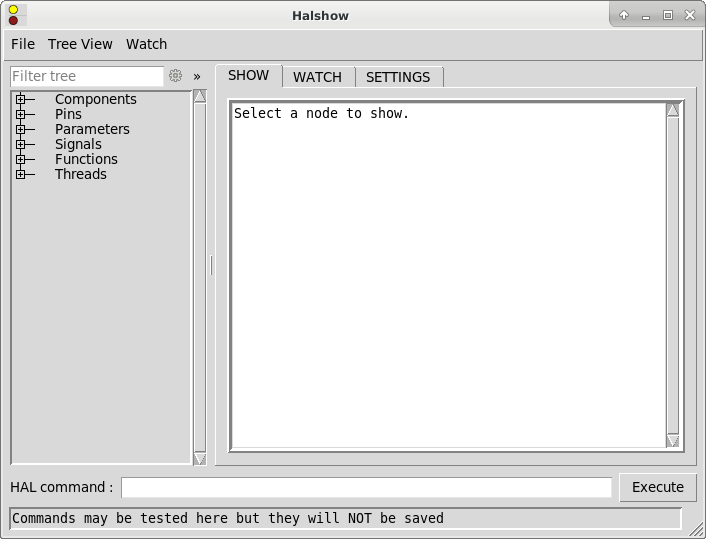
At the left of its display as shown in above figure is a tree view, resembling what you may have seen as file browsers. At the right is a tabbed notebook with tabs for show, watch and settings.
6.2. HAL Tree Area
Per default this entry filters the tree by pin names or tree-nodes by a regular expression. For example, entering "lim-sw" would filter the tree to the following:
joint.0.neg-lim-sw-in
joint.0.pos-lim-sw-in
joint.1.neg-lim-sw-in
joint.1.pos-lim-sw-in
joint.2.neg-lim-sw-in
joint.3.pos-lim-sw-in
If you would like to display all joint.0-related, you have to click the settings icon and select "Full path". Pay attention to escape the regex special characters, so you have to enter "joint\.1\." to explicitly request the dot and not also find joint 10.
The tree shows all of the major parts of a HAL. In front of each is a small plus (+) or minus (-) sign in a box to expand or collapse the corresponding section of the tree.
You can also expand or collapse the tree display using the Tree View menu at the upper left edge of the display.
Under Tree View you will find: Expand All, Collapse All; Expand Pins, Expand Parameters, Expand Signals; and Reload tree view. Reload tree view is useful when new components are loaded during runtime and should be displayed.
6.3. HAL Show Area
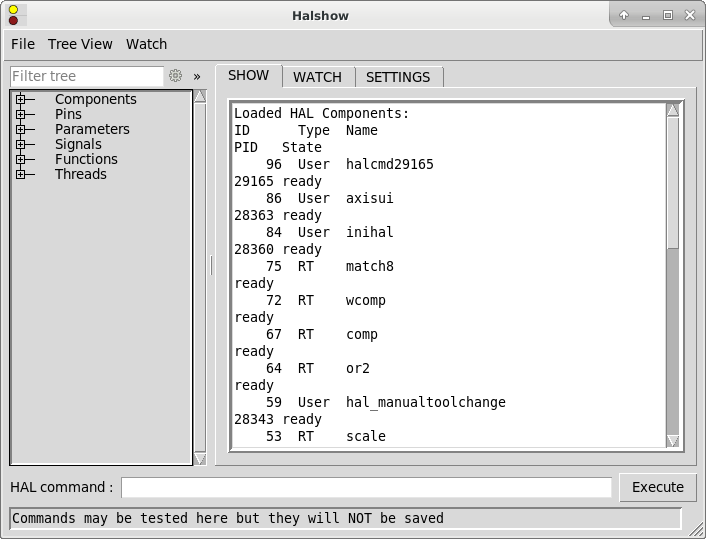
Clicking on the node name, "Components" in the tree for example, will show you (under the "Show" tab) all that HAL knows about the contents of that node. Figure Halshow Show Tab shows a list exactly like you will see if you click the "Components" name. The information display is exactly like those shown in traditional text based HAL analysis tools. The advantage here is that we have mouse click access, access that can be as broad or as focused as you need.
If we take a closer look at the tree display we can see that the six major parts of a HAL can all be expanded at least one level. As these levels are expanded you can get more focused with the reply when you click on the rightmost tree node. You will find that there are some HAL pins and parameters that show more than one reply. This is due to the nature of the search routines in halcmd itself. If you search one pin you may get two, like this:
Component Pins:
Owner  Type  Dir  Value  Name
06     bit    -W   TRUE  parport.0.pin-10-in
06     bit    -W  FALSE  parport.0.pin-10-in-not
The second pin’s name contains the complete name of the first.
6.4. Watch Tab Area
Clicking the watch tab produces a blank canvas. You can add signals and pins to this canvas and watch their values. You can add signals or pins when the watch tab is displayed by clicking on the name of it in the tree view.
The following figure shows this canvas with several pins.
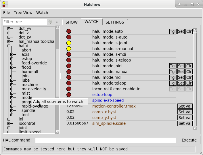
Watch displays bit type (binary) values using colored circles representing LEDs. They show as dark red when a bit signal or pin is false, and as light yellow whenever that signal is true. If you select a pin or signal that is not a bit type (binary) signal, watch will show it as a numerical value. Pins are displayed in black, signals in blue and parameters in brown.
Watch will quickly allow you to test switches or see the effect of changes that you make to LinuxCNC while using the graphical interface. Watch’s refresh rate is a bit slow to see stepper pulses, but you can use it for these if you move an axis very slowly or in very small increments of distance.
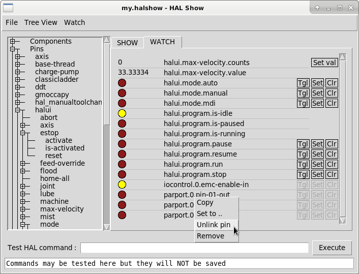
Context Menu
6.5. Command Entry
In the lower part is an entry box to test HAL commands. The commands you enter here and the effect that they have on the running HAL are not saved. They will persist as long as LinuxCNC remains up but are gone as soon as LinuxCNC is.
The entry box labeled "HAL Command:" will accept any of the commands listed for halcmd. These include:
-
loadrt,unloadrt(load/unload real-time module) -
loadusr,unloadusr(load/unload non-realtime component) -
addf,delf(add/delete a function to/from a real-time thread) -
net(create a connection between two or more items) -
setp(set parameter (or pin) to a value)
This little editor will enter a command any time you press enter or push the execute button. An error message from halcmd will be shown when these commands are not properly formed. If you are not certain how to set up a proper command, you’ll need to read again the documentation on halcmd and the specific modules that you are working with.
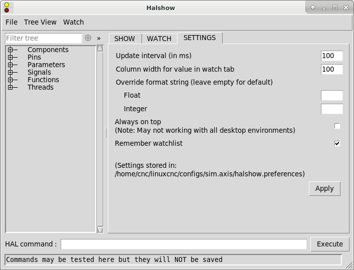
6.6. Settings
6.7. Example/Tutorial
Let’s use this editor to add a differential module to a HAL and connect it to axis position so that we could see the rate of change in position, i.e., acceleration. We first need to load a HAL component named ddt, add it to the servo thread, then connect it to the position pin of a joint. Once that is done we can find the output of the differentiator in halscope. So let’s go.
loadrt ddt
Now look at the components node and you should see ddt in there someplace.
Loaded HAL Components:
ID Type        Name
10 User halcmd29800
09 User halcmd29374
08   RT         ddt
06   RT hal_parport
05   RT    scope_rt
04   RT     stepgen
03   RT      motmod
02 User   iocontrol
Sure enough, there it is. Notice that its ID is 08. Next we need to find out what functions are available with it so we look at functions:
Exported Functions:
Owner  CodeAddr      Arg  FP Users Name
  08   E0B97630 E0DC7674 YES     0 ddt.0
  03   E0DEF83C 00000000 YES     1 motion-command-handler
  03   E0DF0BF3 00000000 YES     1 motion-controller
  06   E0B541FE E0DC75B8  NO     1 parport.0.read
  06   E0B54270 E0DC75B8  NO     1 parport.0.write
  06   E0B54309 E0DC75B8  NO     0 parport.read-all
  06   E0B5433A E0DC75B8  NO     0 parport.write-all
  05   E0AD712D 00000000  NO     0 scope.sample
  04   E0B618C1 E0DC7448 YES     1 stepgen.capture-position
  04   E0B612F5 E0DC7448  NO     1 stepgen.make-pulses
  04   E0B614AD E0DC7448 YES     1 stepgen.update-freq
Here we look for owner #08 and see a function named ddt.0. We should be able to add ddt.0 to the servo thread and it will do its math each time the servo thread is updated. Once again we look up the addf command and find that it uses three arguments like this:
addf <functname> <threadname> [<position>]
We already know the functname=ddt.0 so let’s get the thread name right by expanding the thread node in the tree. Here we see two threads, servo-thread and base-thread. The position of ddt.0 in the thread is not critical. So we add the function ddt.0 to the servo-thread:
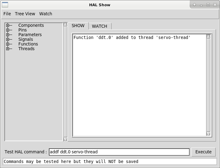
addf ddt.0 servo-thread
This is just for viewing, so we leave position blank and get the last position in the thread. The following figure shows the state of halshow after this command has been issued.
Next we need to connect ddt to something. But how do we know what pins are available? The answer is to look under pins. There we find ddt and see this:
Component Pins:
Owner Type  Dir Value       Name
08    float R-  0.00000e+00 ddt.0.in
08    float -W  0.00000e+00 ddt.0.out
That looks easy enough to understand, but what signal or pin do we want to to connect to it? It could be an axis pin, a stepgen pin, or a signal. We see this when we look at joint.0:
Component Pins:
Owner Type  Dir Value       Name
03    float -W  0.00000e+00 joint.0.motor-pos-cmd ==> Xpos-cmd
So it looks like Xpos-cmd should be a good signal to use. Back to the editor where we enter the following command:
linksp Xpos-cmd ddt.0.in
Now if we look at the Xpos-cmd signal using the tree node we’ll see what we’ve done:
Signals:
Type Value Name
float 0.00000e+00 Xpos-cmd
<== joint.0.motor-pos-cmd
==> ddt.0.in
==> stepgen.0.position-cmd
We see that this signal comes from joint.o.motor-pos-cmd and goes to both ddt.0.in and stepgen.0.position-cmd. By connecting our block to the signal we have avoided any complications with the normal flow of this motion command.
The HAL Show Area uses halcmd to discover what is happening in a running HAL. It gives you complete information about what it has discovered. It also updates as you issue commands from the little editor panel to modify that HAL. There are times when you want a different set of things displayed without all of the information available in this area. That is where the HAL Watch Area is of value.