1. Introducción
En este capítulo trataremos de desmitificar a los sistemas de coordenadas. Es un concepto muy importante para comprender la operación de una máquina CNC, su configuración y su uso.
También mostraremos que es muy interesante usar un punto de referencia en el espacio o en la pieza y hacer que el programa trabaje desde este punto, sin tener en cuenta en dónde esta colocada la pieza en la mesa.
Este capítulo describe los offsets tal como los utiliza LinuxCNC. Éstos incluyen:
-
Coordenadas de la máquina (G53)
-
Nueve offsets del sistema de coordenadas (G54-G59.3)
-
Offsets globales (G92) y locales (G52)
2. Sistema de coordenadas de la máquina
Cuando se inicia LinuxCNC, las posiciones de cada eje definen el origen de la máquina. Cuando se hace home de un eje, el origen de la máquina para ese eje se establece en esa posición home. El origen máquina es el sistema de coordenadas de la máquina en el que se basan todos los demás sistemas de coordenadas. El código G53 puede usarse para moverse en el sistema de coordenadas máquina.
2.1. Movimientos en coordenadas de máquina: G53
Independientemente de cualquier offset que pudiera estar activo, un G53 en una línea de código indica al intérprete moverse a las posiciones reales de los ejes (posiciones absolutas) especificadas. Por ejemplo:
G53 G0 X0 Y0 Z0
moverá de la posición actual a la posición donde las coordenadas de máquina de los tres ejes sean cero. Puedes usar este comando si tienes una posición fija para el cambio de herramienta o si tu máquina tiene un cambiador automático de herramienta. También puedes usar este comando para despejar el área de trabajo y acceder a la pieza de trabajo en la mordaza.
G53 es un comando no modal. Debe usarse en cada bloque en el que se desee un movimiento en el sistema coordenado de la máquina.
3. Sistemas de coordenadas
-
G54 - usa el sistema de coordenadas 1
-
G55 - usa el sistema de coordenadas 2
-
G56 - usa el sistema de coordenadas 3
-
G57 - usa el sistema de coordenadas 4
-
G58 - usa el sistema de coordenadas 5
-
G59 - usa el sistema de coordenadas 6
-
G59.1 - usa el sistema de coordenadas 7
-
G59.2 - usa el sistema de coordenadas 8
-
G59.3 - usa el sistema de coordenadas 9
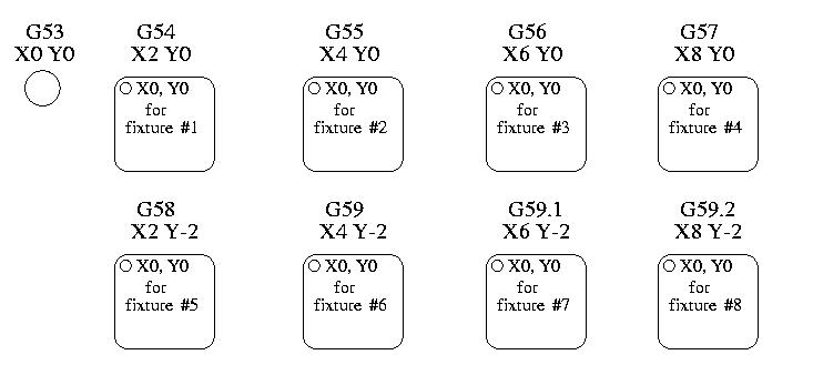
Los offsets del sistema de coordenadas se utilizan para desplazar cada sistema de coordenadas desde el sistema de coordenadas de la máquina. Esto permite que el código G se programe para la pieza sin importar la ubicación de la pieza en la máquina. El uso de offsets del sistema de coordenadas te permitirá mecanizar piezas en múltiples ubicaciones con el mismo código G.
Los valores de los offsets se almacenan en el archivo VAR solicitado por el archivo INI durante el inicio de LinuxCNC. En el ejemplo de abajo, el cual usa G55, la posición de cada eje para el origen G55 se almacena en una variable numerada.
En el esquema de archivo VAR, el primer número de variable almacena el offset X, el segundo, el offset Y, y así sucesivamente para los nueve ejes. Hay conjuntos numerados como este para cada uno de los offsets de sistema de coordenadas.
Cada una de las interfaces gráficas tiene una forma de establecer valores para estos offsets. También puede establecer estos valores editando el propio archivo VAR y reinicializando luego LinuxCNC para que lea los nuevos valores. Sin embargo, esta no es la forma recomendada. El uso de G10, G52, G92, G28.1, etc. son mejores formas de establecer las variables. Para nuestro ejemplo, editaremos directamente el archivo para que G55 tome los valores siguientes:
| Eje | Variable | Valor |
|---|---|---|
X |
5241 |
2.000000 |
Y |
5242 |
1.000000 |
Z |
5243 |
-2.000000 |
A |
5244 |
0.000000 |
B |
5245 |
0.000000 |
C |
5246 |
0.000000 |
U |
5247 |
0.000000 |
V |
5248 |
0.000000 |
W |
5249 |
0.000000 |
Deberías leer esto como mover las posiciones cero de G55 a X = 2 unidades, Y = 1 unidad, y Z = -2 unidades desde la posición de cero absoluto.
Una vez que hay valores asignados, una llamada a G55 en un bloque de programa desplaza la referencia cero absoluta por los valores almacenados. La siguiente línea movería cada eje a la nueva posición cero. A diferencia de G53, G54 hasta G59.3 son comandos modales. Actuarán en todos los bloques de código después de que uno de ellos se ha establecido. El programa que podría ejecutarse usando offsets de fijaciones requeriría solo una coordenada de referencia para cada una de las ubicaciones y todo el trabajo se realizaria allí. El siguiente código se ofrece como un ejemplo de cómo hacer un cuadrado usando los offsets G55 que configuramos arriba.
G55; utilizar el sistema de coordenadas 2
G0 X0 Y0 Z0
G1 F2 Z-0.2000
X1
Y1
X0
Y0
G0 Z0
G54; utilizar el sistema de coordenadas 1
G0 X0 Y0 Z0
M2
En este ejemplo, el G54 cerca del final deja el sistema de coordenadas G54 con todos los offsets a cero para que haya un código modal basado en ejes absolutos de máquina. Este programa asume que lo hemos hecho y usamos el comando final como un comando para cero máquina. Hubiera sido posible usar G53 y llegar al mismo lugar pero ese comando no habría sido modal y cualquier comando emitido después hubiera vuelto a usar los offsets G55 porque ese sistema de coordenadas todavía estaría en vigor.
[source,ngc]
G54     usa parámetros del sistema de coordenadas 1
G55     usa parámetros del sistema de coordenadas 2
G56     usa parámetros del sistema de coordenadas 3
G57     usa parámetros del sistema de coordenadas 4
G58     usa parámetros del sistema de coordenadas 5
G59     usa parámetros del sistema de coordenadas 6
G59.1   usa parámetros del sistema de coordenadas 7
G59.2   usa parámetros del sistema de coordenadas 8
G59.3   usa parámetros del sistema de coordenadas 9
3.1. Sistema de coordenadas predeterminado
Otra variable en el archivo VAR se vuelve importante cuando pensamos en sistemas de offsets. Esta variable es la 5220. En los archivos predeterminados, su valor se establece en 1.00000. Esto significa que cuando LinuxCNC se inicia, debería usar el primer sistema de coordenadas como el predeterminado. Si se configura a 9.00000 usaría el noveno sistema de offsets como predeterminado al iniciar o reiniciar. Cualquier valor que no sea un entero (decimal realmente) entre 1 y 9, o si falta la variable 5220 hará que LinuxCNC vuelva al valor predeterminado de 1.00000 al inicio.
3.2. Configuración de offsets de sistema de coordenadas
El comando G10 L2x se puede usar para establecer los offsets de sistema de coordenadas:
|
Nota
|
Aquí solo damos un vistazo, ve a las secciones de código G para una descripción completa. |
4. Offsets locales y globales
4.1. El comando G52
G52 se usa en un programa de pieza como un "offset del sistema de coordenadas local" temporal dentro del sistema de coordenadas de la pieza de trabajo. Un ejemplo de caso de uso es cuando se mecanizan varias características idénticas en diferentes ubicaciones de una pieza. Para cada una, G52 programa un punto de referencia local dentro de las coordenadas de pieza, y se llama a un subprograma para maquinar la característica relativa a ese punto.
Los offsets de ejes G52 se programan relativos a las coordenadas de offset de la pieza de trabajo G54 a G59.3. Como un offset local, G52 se aplica después del offset de la pieza de trabajo, incluida la rotación. Por lo tanto, una característica parcial será mecanizada de forma idéntica en cada parte, independientemente de la orientación de la parte en el palet.
|
Atención
|
En otros intérpretes de código G, G52 no persiste después de reinicio de la máquina M02 o M30, al asignar y desasignar un offset temporal dentro de un ámbito localizado de un programa de parte. En LinuxCNC, G52 comparte parámetros con G92, el cual por razones históricas persiste esos parámetros. Ver G92 Precauciones con persistencia a continuación. |
|
Atención
|
G52 y G92 comparten los mismos registros de offset. Por lo tanto, usar G52 anulará cualquier configuración G92 previa, y G52 persistirá después de un reinicio de máquina cuando la persistencia de G92 este activada. Estas interacciones pueden resultar en offsets inesperados. Ver Precauciones de interacción G92 y G52 abajo. |
La programación de G52 X1 Y2 da offsets al sistema de coordenadas actual de la pieza de trabajo, 1 para eje X y 2 para eje Y. Por consiguiente, en el DRO las coordenadas X e Y de la posición actual de la herramienta se reducirán en 1 y 2, respectivamente. Los ejes sin establecer en el comando, como Z en el ejemplo anterior, no se verán afectados: cualquier offset Z G52 previo permanecerá vigente, y en caso de haberlo, el offset Z será cero.
El offset local temporal puede cancelarse con G52 X0 Y0. Cualquier eje no puesto a cero explícitamente retendrá el offset anterior.
G52 comparte los mismos registros que G92, por lo que G52 es visible en el DRO y vista previa, etiquetado como G92.
5. G92 Offsets de ejes
G92 is the most misunderstood and cleverest command programmable with LinuxCNC. The way it works has changed a bit between the first versions and the current one. These changes have doubt baffled many users. They should be seen as a command producing a temporary offset, which applies to all the other offsets.
5.1. The G92 commands
G92 is typically used in two conceptually different ways: as a "global coordinate system offset" or as a "local coordinate system offset".
The G92 set of commands includes:
-
G92 - Este comando, cuando se usa con nombres de eje, establece valores para las variables de offset.
-
G92.1 - This command sets zero values to the G92 variables.
-
G92.2 - Este comando suspende G92, pero no pone a cero las variables.
-
G92.3 - This command applies offset values that have been suspended.
As a global offset, G92 is used to shift all workpiece coordinate systems G54 through G59.3. An example use case is when machining several identical parts in fixtures with known locations on a pallet, but the pallet location may change between runs or between machines. Each fixture location offset, relative to a reference point on the pallet, is preset in one of the workpiece coordinate systems, G54 through G59.3, and G92 is used to "touch off" on the pallet reference point. Then, for each part, the corresponding workpiece coordinate system is selected and the part program is executed.
|
Nota
|
G10 R- workpiece coordinate system rotation is specific to the rs274ngc interpreter, and the G92 offset is applied after rotation. When using G92 as a global offset, workpiece coordinate system rotations may have unexpected results. |
As a local coordinate system, G92 is used as a temporary offset within the workpiece coordinate system. An example use case is when machining a part with several identical features at different locations. For each feature, G92 is used to set a local reference point, and a subprogram is called to machine the feature starting at that point.
|
Nota
|
The use of G92 is discouraged for programming with local coordinate systems in a part program. Instead, see G52, a local coordinate system offset more intuitive when desired offset relative to the workpiece is known but current tool location may not be known. |
Programming G92 X0 Y0 Z0 sets the current tool location to the coordinates X0, Y0, and Z0, without motion. G92 does not work from absolute machine coordinates. It works from current location.
G92 also works from current location as modified by any other offsets that are in effect when the G92 command is invoked. While testing for differences between work offsets and actual offsets it was found that a G54 offset could cancel out a G92 and thus give the appearance that no offsets were in effect. However, the G92 was still in effect for all coordinates and did produce expected work offsets for the other coordinate systems.
By default, G92 offsets are restored after the machine is started. Programmers that wish for Fanuc behavior, where G92 offsets are cleared at machine start and after a reset or program end, may disable G92 persistence by setting DISABLE_G92_PERSISTENCE = 1 in the [RS274NGC] section of the INI file.
|
Nota
|
It is good practice to clear the G92 offsets at the end of their use with G92.1 or G92.2. When starting up LinuxCNC with G92 persistence enabled (the default), any offsets in the G92 variables will be applied when an axis is homed. See G92 Persistence Cautions below. |
5.2. Setting G92 Values
There are at least two ways to set G92 values:
-
Con un click derecho en la posición mostrada en tklinuxcnc, se abre una ventana donde es posible introducir un valor.
-
With the G92 command
Both work from the current position of the axis that should be moved.
Programming G92 X Y Z A B C U V W sets the values of the G92 variables so that each axis takes the value associated with its name. Those values are assigned to the current position of the axes. These results satisfy to paragraphs one and two of the NIST document.
G92 commands work from current axis location and add and subtract correctly to give the current axis position the value assigned by the G92 command. The effects work even though previous offsets are in.
So if the X axis is currently showing 2.0000 as its position a G92 X0 will set an offset of -2.0000 so that the current location of X becomes zero. A G92 X2 will set an offset of 0.0000 and the displayed position will not change. A G92 X5.0000 will set an offset of 3.0000 so that the current displayed position becomes 5.0000.
5.3. G92 Persistence Cautions
By default, the values of a G92 offset will be saved in the VAR file and be restored after a machine reset or startup.
The G92 parameters are:
-
5210 - Enable/disable flag (1.0/0.0)
-
5211 - X Axis Offset
-
5212 - Y Axis Offset
-
5213 - Z Axis Offset
-
5214 - A Axis Offset
-
5215 - B Axis Offset
-
5216 - C Axis Offset
-
5217 - U Axis Offset
-
5218 - V Axis Offset
-
5219 - W Axis Offset
where 5210 is the G92 enable flag (1 for enabled, 0 for disabled) and 5211 to 5219 are the axis offsets. If you are seeing unexpected positions as the result of a commanded move, as a result of storing an offset in a previous program and not clearing them at the end then issue a G92.1 in the MDI window to clear the stored offsets.
If G92 values exist in the VAR file when LinuxCNC starts up, the G92 values in the var file will be applied to the values of the current location of each axis. If this is home position and home position is set as machine zero everything will be correct. Once home has been established using real machine switches, or by moving each axis to a known home position and issuing an axis home command, any G92 offsets will be applied. If you have a G92 X1 in effect when you home the X axis the DRO will read X: 1.000 instead of the expected X: 0.000 because the G92 was applied to the machine origin. If you issue a G92.1 and the DRO now reads all zeros then you had a G92 offset in effect when you last ran LinuxCNC.
Unless your intention is to use the same G92 offsets in the next program, the best practice is to issue a G92.1 at the end of any G code files where you use G92 offsets.
When a program is aborted during processing that has G92 offsets in effect a startup will cause them to become active again. As a safeguard, always have your preamble to set the environment as you expect it. Additionally, G92 persistence may be disabled by setting DISABLE_G92_PERSISTENCE = 1 in the [RS274NGC] section of the INI file.
5.4. G92 and G52 Interaction Cautions
G52 and G92 share the same offset registers. Unless G92 persistence is disabled in the INI file (see G92 Commands), G52 offsets will also persist after machine reset, M02 or M30. Beware that a G52 offset in effect during a program abort may result in unintended offsets when the next program is run. See G92 Persistence Cautions above.
6. Sample Programs Using Offsets
6.1. Sample Program Using Workpiece Coordinate Offsets
This sample engraving project mills a set of four .1 radius circles in roughly a star shape around a center circle. We can setup the individual circle pattern like this.
G10 L2 P1 X0 Y0 Z0 (ensure that G54 is set to machine zero)
G0 X-0.1 Y0 Z0
G1 F1 Z-0.25
G3 X-0.1 Y0 I0.1 J0
G0 Z0
M2
Podemos emitir un conjunto de comandos para crear offsets para los otros cuatro círculos, como esto.
G10 L2 P2 X0.5 (offsets G55 X value by 0.5 inch)
G10 L2 P3 X-0.5 (offsets G56 X value by -0.5 inch)
G10 L2 P4 Y0.5 (offsets G57 Y value by 0.5 inch)
G10 L2 P5 Y-0.5 (offsets G58 Y value by -0.5 inch)
We put these together in the following program:
(a program for milling five small circles in a diamond shape)

G10 L2 P1 X0 Y0 Z0 (ensure that G54 is machine zero)
G10 L2 P2 X0.5 (offsets G55 X value by 0.5 inch)
G10 L2 P3 X-0.5 (offsets G56 X value by -0.5 inch)
G10 L2 P4 Y0.5 (offsets G57 Y value by 0.5 inch)
G10 L2 P5 Y-0.5 (offsets G58 Y value by -0.5 inch)

G54 G0 X-0.1 Y0 Z0 (center circle)
G1 F1 Z-0.25
G3 X-0.1 Y0 I0.1 J0
G0 Z0

G55 G0 X-0.1 Y0 Z0 (first offset circle)
G1 F1 Z-0.25
G3 X-0.1 Y0 I0.1 J0
G0 Z0

G56 G0 X-0.1 Y0 Z0 (second offset circle)
G1 F1 Z-0.25
G3 X-0.1 Y0 I0.1 J0
G0 Z0

G57 G0 X-0.1 Y0 Z0 (third offset circle)
G1 F1 Z-0.25
G3 X-0.1 Y0 I0.1 J0
G0 Z0

G58 G0 X-0.1 Y0 Z0 (fourth offset circle)
G1 F1 Z-0.25
G3 X-0.1 Y0 I0.1 J0
G54 G0 X0 Y0 Z0

M2
Now comes the time when we might apply a set of G92 offsets to this program. You’ll see that it is running in each case at Z0. If the mill were at the zero position, a G92 Z1.0000 issued at the head of the program would shift everything an inch. You might also shift the whole pattern around in the XY plane by adding some X and Y offsets with G92. If you do this you should add a G92.1 command just before the M2 that ends the program. If you do not, other programs that you might run after this one will also use that G92 offset. Furthermore it would save the G92 values when you shut down the LinuxCNC and they will be recalled when you start up again.
6.2. Sample Program Using G52 Offsets
(To be written)