1. Introducción
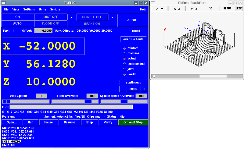
TkLinuxCNC is one of the first graphical front-ends for LinuxCNC. It is written in Tcl and uses the Tk toolkit for the display. Being written in Tcl makes it very portable (it runs on a multitude of platforms). A separate backplot window can be displayed as shown.
2. Getting Started
To select TkLinuxCNC as the front-end for LinuxCNC, edit the INI file. In the section [DISPLAY] change the DISPLAY line to read
DISPLAY = tklinuxcnc
Then, start LinuxCNC and select that INI file. The sample configuration sim/tklinuxcnc/tklinuxcnc.ini is already configured to use TkLinuxCNC as its front-end.
When LinuxCNC is launched the TKLinuxCNC window is opened.
2.1. Una sesión típica con TkLinuxCNC
-
Start LinuxCNC and select a configuration file.
-
Clear the E-STOP condition and turn the machine on (by pressing F1 then F2).
-
Home each axis.
-
Load the file to be milled.
-
Put the stock to be milled on the table.
-
Set the proper offsets for each axis by jogging and either homing again or right-clicking an axis name and entering an offset value.
[For some of these actions it might be necessary to change the mode LinuxCNC is currently running in.]
-
Run the program.
-
Para fresar el mismo archivo, regresar al paso 6. Para fresar un archivo distinto regrese al paso 4. Al terminar, salga de LinuxCNC.
3. Elements of the TkLinuxCNC window
The TkLinuxCNC window contains the following elements:
-
A menubar that allows you to perform various actions
-
A set of buttons that allow you to change the current working mode, start/stop spindle and other relevant I/O
-
Status bar for various offset related displays
-
Coordinate display area
-
A set of sliders which control Jogging speed, Feed Override, and Spindle speed Override which allow you to increase or decrease those settings
-
Manual data input text box MDI
-
Status bar display with active G-codes, M-codes, F- and S-words
-
Interpreter related buttons
-
A text display area that shows the G-code source of the loaded file
3.1. Main buttons
From left to right, the buttons are:
-
Machine enable: ESTOP > ESTOP RESET > ON
-
Toggle mist coolant
-
Decrease spindle speed
-
Set spindle direction SPINDLE OFF > SPINDLE FORWARD . SPINDLE REVERSE
-
Increase spindle speed
-
Abort
then on the second line:
-
Operation mode: MANUAL > MDI > AUTO
-
Toggle flood coolant
-
Toggle spindle brake control
3.2. Offset display status bar
The Offset display status bar displays the currently selected tool (selected with Txx M6), the tool length offset (if active), and the work offsets (set by right-clicking the coordinates).
3.3. Coordinate Display Area
The main part of the display shows the current position of the tool. The color of the position readout depends on the state of the axis. If the axis is unhomed the axis will be displayed in yellow letters. Once homed it will be displayed in green letters. If there is an error with the current axis TkLinuxCNC will use red letter to show that. (for example if an hardware limit switch is tripped).
Para interpretar apropiadamente esos números, refiérase a los botones de opción de la derecha. Si la posición es Máquina, entonces el número mostrado esta en el sistema coordenado de la máquina. Si es Relativo, entonces el número mostrado esta en el desplazamiento del sistema coordenado. Opciones mas abajo pueden ser Real o Comandada. Real se refiere a la retroalimentación de los codificadores (si tiene una máquina servo), y Comandada se refiere a la posición ordenada enviada a los motores. Estos valores pueden diferir por razones distintas: error de seguimiento, banda muerta, resolución del codificador o tamaño de paso. Por ejemplo, si ordena un movimiento a X 0.0033 en su fresadora, pero un paso de su motor paso a paso es 0.00125, la posición Comandada será 0.0033, pero la posición Real será 0.0025 (2 pasos) o 0.00375 (3 pasos).
Another set of radio buttons allows you to choose between joint and world view. These make little sense on a normal type of machine (e.g. trivial kinematics), but help on machines with non-trivial kinematics like robots or stewart platforms. (you can read more about kinematics in the Integrator Manual).
When the machine moves, it leaves a trail called the backplot. You can start the backplot window by selecting View→Backplot.
3.4. TkLinuxCNC Interpreter / Automatic Program Control

The buttons in the lower part of TkLinuxCNC are used to control the execution of a program:
+ * Open to load a program, * Verify to check it for errors, * Run to start the actual cutting, * Pause to stop it while running, * Resume to resume an already paused program, * Step to advance one line in the program and * Optional Stop to toggle the optional stop switch (if the button is green the program execution will be stopped on any M1 encountered).
When the program is running, the line currently being executed is highlighted in white. The text display will automatically scroll to show the current line.
3.5. Manual Control
TkLinuxCNC le permite mover manualmente la máquina. Esta acción se conoce como trotar. Primero, seleccione el eje a mover haciendo clic en él. Luego, haga clic y mantenga presionado el botón + o - dependiendo de la dirección de movimiento deseada. Los primeros cuatro ejes también pueden moverse con las teclas de flecha (X e Y), Teclas PAGE UP y PAGE DOWN (Z), y las teclas [ y ] (A/4th).
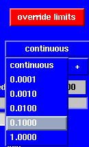
+ Si se selecciona Continuo, el movimiento continuará mientras el botón o la tecla se presiona. Si se selecciona otro valor, la máquina se moverá exactamente la distancia mostrada cada vez que se hace clic en el botón o se presiona la tecla. Los valores disponibles son:
+
1.0000, 0.1000, 0.0100, 0.0010, 0.0001+ By pressing Home or the HOME key, the selected axis will be homed. Depending on your configuration, this may just set the axis value to be the absolute position 0.0, or it may make the machine move to a specific home location through use of home switches. See the Homing Chapter for more information.
+ By pressing Override Limits, the machine will temporarily be permitted to jog outside the limits defined in the INI file. (Note: if Override Limits is active the button will be displayed using a red color).
The button on the first row selects the direction for the spindle to rotate: Counterclockwise, Stopped, Clockwise. The buttons next to it allow the user to increase or decrease the rotation speed. The button on the second row allows the spindle brake to be engaged or released. Depending on your machine configuration, not all the items in this group may have an effect.
The two buttons allow the Mist and Flood coolants to be turned on and off. Depending on your machine configuration, not all the items in this group may appear.
3.6. Code Entry
Manual Data Input (también llamada MDI), permite ingresar programas en código G manualmente, una línea a la vez. Cuando la máquina no está encendida, y no esta en modo MDI, los controles de captura de código no están disponibles.

This allows you to enter a G-code command to be executed. Execute the command by pressing Enter.
Se muestran los códigos modales que están activos en el intérprete. Por ejemplo, G54 indica que el offset G54 se aplica a todas las coordenadas que se introduzcan.
3.7. Jog Speed
By moving this slider, the speed of jogs can be modified. The numbers above refer to axis units / second. The text box with the number is clickable. Once clicked a popup window will appear, allowing for a number to be entered.
3.8. Feed Override
By moving this slider, the programmed feed rate can be modified. For instance, if a program requests F60 and the slider is set to 120%, then the resulting feed rate will be 72. The text box with the number is clickable. Once clicked a popup window will appear, allowing for a number to be entered.
3.9. Spindle speed Override
El control deslizante de anulación de velocidad del husillo funciona exactamente como el control deslizante de alimentación, pero controla la velocidad del husillo. Por ejemplo, si un programa solicita S500 (velocidad del husillo de 500 RPM) y el control deslizante se establece en 80%, entonces la velocidad del husillo resultante será 400 RPM. El control deslizante tienen valores mínimo y un máximo definidos en el archivo INI; si faltasen, el deslizante permanecerá en 100%. Se puede hacer clic en el cuadro de texto con el número, al hacerlo aparecerá una ventana emergente que permitirá capturar un número.
4. Keyboard Controls
Almost all actions in TkLinuxCNC can be accomplished with the keyboard. Many of the shortcuts are unavailable when in MDI mode.
The most frequently used keyboard shortcuts are shown in the following table.
| Keystroke | Action Taken |
|---|---|
F1 |
Toggle Emergency Stop |
F2 |
Turn machine on/off |
`, 1 .. 9, 0 |
Set feed override from 0% to 100% |
X, ` |
Activate first axis |
Y, 1 |
Activate second axis |
Z, 2 |
Activate third axis |
A, 3 |
Activate fourth axis |
Home |
Send active axis Home |
Left, Right |
Jog first axis |
Up, Down |
Jog second axis |
Pg Up, Pg Dn |
Jog third axis |
[, ] |
Jog fourth axis |
ESC |
Stop execution |