1. Introducción
GMOCCAPY is a GUI for LinuxCNC, designed to be used with a touch screen, but can also be used on normal screens with a mouse or hardware buttons and MPG wheels, as it presents HAL Pins for the most common needs. Please find more information in the following.
Ofrece la posibilidad de mostrar hasta 4 ejes, admite un modo de torno para herramienta normal y posterior, que puede adaptarse a casi cualquier necesidad, ya que GMOCCAPY soporta pestañas y paneles laterales incrustados. Como un buen ejemplo de esto, puede verse gmoccapy_plasma.
GMOCCAPY 3 does support up to 9 axes and 9 joints. As GMOCCAPY 3 has been changed in code to support the joint / axis changes in LinuxCNC it does not work on 2.7 or 2.6 branch!
It has support for integrated virtual keyboard (onboard or matchbox-keyboard), so there is no need for a hardware keyboard or mouse, but it can also be used with that hardware. GMOCCAPY offers a separate settings page to configure most settings of the GUI without editing files.
GMOCCAPY can be localized very easy, because the corresponding files are separated from the linuxcnc.po files, so there is no need to translate unneeded stuff. If you want to contribute a translation, please use the web based translation editor Weblate. For more information see the section Translations

2. Requirements
GMOCCAPY 3 se ha probado en Debian Jessie, Debian Stretch y MINT 18 con la rama master versión 2.8 de LinuxCNC. Es totalmente compatible con los cambios articulaciones/ejes de LinuxCNC, haciéndolo adecuado como GUI para Scara, Robots o cualquier otra configuración con más articulaciones que ejes. También soporta configuraciones de pórtico. Si usas otras versiones, por favor, informar sobre problemas y/o soluciones en foro LinuxCNC o en Foro CNC Ecke Alemán o en Lista de correo de usuarios de LinuxCNC.
The minimum screen resolution for GMOCCAPY for the normal layout (without side panels) is 980 x 750 Pixel, so it should fit to every standard screen. It is recommended to use screens with minimum resolution of 1024x768. There is also a configuration which fits for 800x600 screens (introduced in GMOCCAPY 3.4.8).
3. How to get GMOCCAPY
GMOCCAPY 3 is included in the standard distribution of LinuxCNC since release 2.7. So the easiest way to get GMOCCAPY on your controlling PC is just to download the ISO and install it from the CD/DVD/USB-stick. This allows you to receive updates with the regular Debian packages.
In the release notes aka changelist you can track the latest bugfixes and features.
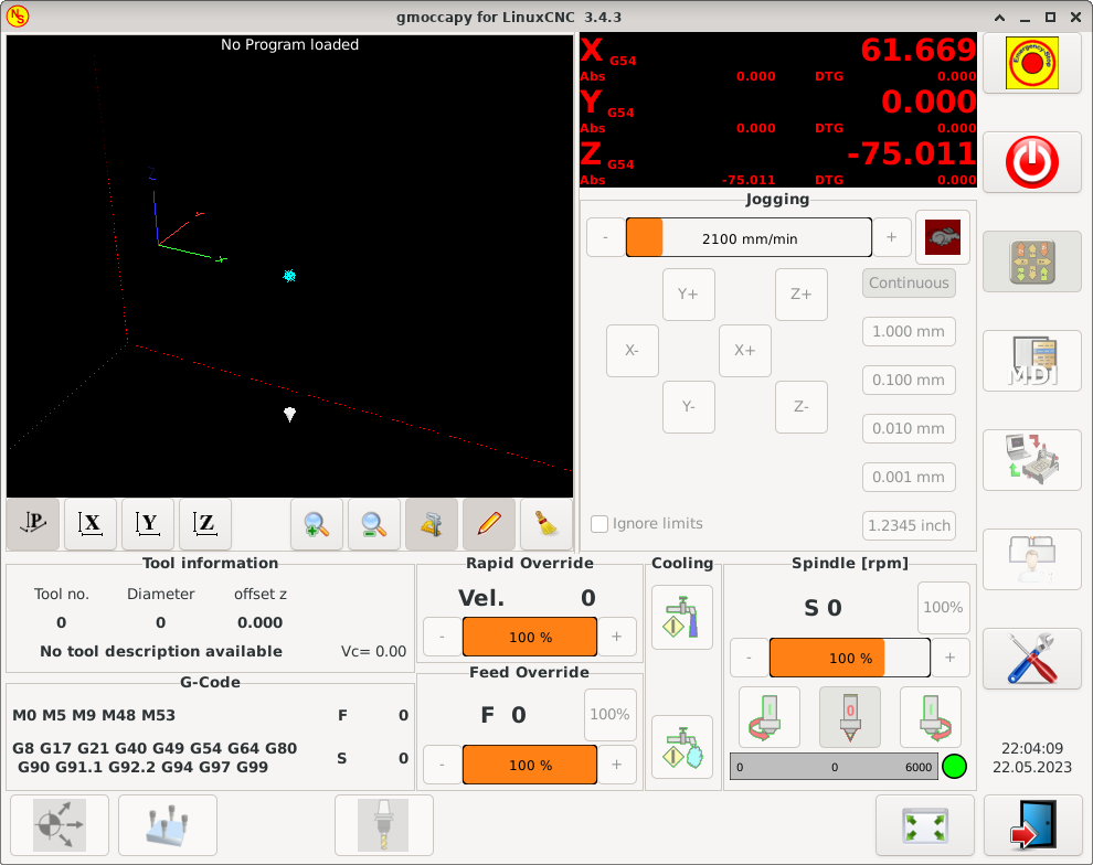
Obtendrá una pantalla similar a la siguiente (el diseño puede variar dependiendo de su configuración.):
4. Basic Configuration
GMOCCAPY 3 supports the following command line options:
-
-user_mode: si está configurado, el botón de configuración se deshabilitará, por lo que los operadores normales de la máquina no podrán editar la configuración.
-
-logo <ruta al archivo de logotipo>: si se proporciona, el logotipo ocultará la pestaña del botón de jog en modo manual, esto solo es útil para máquinas con botón de hardware para jogging y selección de incrementos.
There is really not to much to configure just to run GMOCCAPY, but there are some points you should take care off if you want to use all the features of the GUI.
You will find a lot of simulation configurations (INI files) included, just to show the basics:
-
gmoccapy.ini
-
gmoccapy_4_axis.ini
-
lathe_configs/gmoccapy_lathe.ini
-
lathe_configs/gmoccapy_lathe_imperial.ini
-
gmoccapy_left_panel.ini
-
gmoccapy_right_panel.ini
-
gmoccapy_messages.ini
-
gmoccapy_pendant.ini
-
gmoccapy_sim_hardware_button.ini
-
gmoccapy_tool_sensor.ini
-
gmoccapy_with_user_tabs.ini
-
gmoccapy_XYZAB.ini
-
gmoccapy_XYZAC.ini
-
gmoccapy_XYZCW.ini
-
gmoccapy-JA/Gantry/gantry_mm.ini
-
gmoccapy-JA/scara/scara.ini
-
gmoccapy-JA/table-rotary-tilting/xyzac-trt.ini
-
and a lot more …
The names should explain the main intention of the different INI files.
If you use an existing configuration of your machine, just edit your INI according to this document.
Echemos un vistazo más de cerca al archivo INI y lo que necesita incluir para usar GMOCCAPY en su máquina:
4.1. The DISPLAY Section
[DISPLAY]
DISPLAY = gmoccapy
PREFERENCE_FILE_PATH = gmoccapy_preferences
MAX_FEED_OVERRIDE = 1.5
MAX_SPINDLE_OVERRIDE = 1.2
MIN_SPINDLE_OVERRIDE = 0.5
DEFAULT_SPINDLE_SPEED = 500
LATHE = 1
BACK_TOOL_LATHE = 1
PROGRAM_PREFIX = ../../nc_files/
-
DISPLAY = gmoccapy - This tells LinuxCNC to use GMOCCAPY.
-
PREFERENCE_FILE_PATH - Gives the location and name of the preferences file to be used. In most cases this line will not be needed, it is used by GMOCCAPY to store your settings of the GUI, like themes, DRO units, colors, and keyboard settings, etc., see settings page for more details.
NotaIf no path or file is given, GMOCCAPY will use as default <your_machinename>.pref, if no machine name is given in your INI File it will use gmoccapy.pref. The file will be stored in your config directory, so the settings will not be mixed if you use several configs. If you only want to use one file for several machines, you need to include PREFERENCE_FILE_PATHin your INI. -
MAX_FEED_OVERRIDE = 1.5 - Sets the maximum feed override, in the example given, you will be allowed to override the feed by 150%.
NotaSi no se da ningún valor, se establecerá en 1.0. -
MIN_SPINDLE_OVERRIDE = 0.5 and MAX_SPINDLE_OVERRIDE = 1.2 - Will allow you to change the spindle override within a limit from 50% to 120%.
NotaSi no se dan valores, MIN se establecerá en 0.1 y MAX en 1.0. -
LATHE = 1 - Set the screen layout to control a lathe.
-
BACK_TOOL_LATHE = 1 - Is optional and will switch the X axis in a way you need for a back tool lathe. Also the keyboard shortcuts will react in a different way. It is allowed with GMOCCAPY to configure a lathe also with additional axes, so you may use also a XZCW config for a lathe.
SugerenciaConsulte también la sección específica del torno. -
PROGRAM_PREFIX = ../../nc_files/ - Is the entry to tell LinuxCNC/GMOCCAPY where to look for the NGC files.
NotaIf not specified, GMOCCAPY will look in the following order for NGC files: First linuxcnc/nc_filesand then the users home directory. -
DEFAULT_SPINDLE_SPEED - Start value for "Starting RPM" if value not present in preferences file or file is not present. Will have no effect with valid preferences file.
-
MIN_ANGULAR_VELOCITY - Establece la velocidad de trote mínima de la máquina para ejes rotatorios.
-
MAX_ANGULAR_VELOCITY - Establece la velocidad máxima de trote de la máquina para ejes rotatorios.
-
DEFAULT_ANGULAR_VELOCITY - Sets the default jog velocity of the machine for rotary axes.
4.2. The TRAJ Section
-
DEFAULT_LINEAR_VELOCITY = 85.0 - Sets the default jog velocity of the machine.
NotaSi no se proporciona, se utilizará la mitad de MAX_LINEAR_VELOCITY. Si ese valor tampoco se da, se predeterminará a 180. -
MAX_LINEAR_VELOCITY = 230.0 - Establece la velocidad máxima de la máquina. Este valor también será la velocidad de trote lineal máxima.
NotaPredeterminado a 600 si no se asigna.
4.3. Macro Buttons
You can add macros to GMOCCAPY, similar to Touchy’s way. A macro is nothing else than a NGC file. You are able to execute complete CNC programs in MDI mode by just pushing one button. To do so, you first have to specify the search path for macros:
Establece la ruta para buscar macros y otras subrutinas. Si quiere usar varias rutas de subrutinas, simplemente sepárelas con ":".
Then you just have to add a section like this:
[MACROS]
MACRO = i_am_lost
MACRO = hello_world
MACRO = jog_around
MACRO = increment xinc yinc
MACRO = go_to_position X-pos Y-pos Z-pos
Then you have to provide the corresponding NGC files which have to follow these rules:
-
El nombre del archivo debe ser exactamente el mismo que el nombre mencionado en la linea MACRO, con la extensión ".ngc" (sensible a mayúsculas).
-
El archivo debe contener una subrutina como: O<i_am_lost> sub; el nombre de la subrutina debe coincidir exactamente (distingue entre mayúsculas y minúsculas) con el nombre de la macro.
-
El archivo debe terminar con un endsub O<i_am_lost> endsub seguido de un comando M2.
-
The files need to be placed in a folder specified in your INI file by SUBROUTINE_PATH in the RS274NGC section
The code between sub and endsub will be executed by pushing the corresponding macro button.
|
Nota
|
A maximum of 16 macros will be shown in the GUI. Due to space reasons you may need to click on an arrow to switch the page and display hidden macro buttons. The macro buttons will be displayed in the order of the INI entries. It is no error placing more than 16 macros in your INI file, they will just not be shown. |
|
Nota
|
You will find the sample macros in a folder named macros placed in the GMOCCAPY sim folder. If you have given several subroutine paths, they will be searched in the order of the given paths. The first file found will be used. |
GMOCCAPY will also accept macros asking for parameters like:
[MACROS]
MACRO = go_to_position X-pos Y-pos Z-pos
The parameters must be separated by spaces. This example calls a file go_to_position.ngc with the following content:
; Test file "go to position"
; will jog the machine to a given position

O<go_to_position> sub

G17
G21
G54
G61
G40
G49
G80
G90

;#1 = <X-Pos>
;#2 = <Y-Pos>
;#3 = <Z-Pos>

(DEBUG, Will now move machine to X = #1 , Y = #2 , Z = #3)
G0 X #1 Y #2 Z #3

O<go_to_position> endsub
M2
After pushing the execute macro button, you will be asked to enter the values for X-pos Y-pos Z-pos and the macro will only run if all values have been given.
|
Nota
|
Si desea usar una macro sin ningún movimiento, vea también las notas en problemas conocidos. |

4.4. Pestañas y paneles incrustados
You can add embedded programs to GMOCCAPY like you can do in AXIS, Touchy and Gscreen. All is done by GMOCCAPY automatically if you include a few lines in your INI file in the DISPLAY section.
Si nunca ha usado un panel Glade, se recomienda leer la excelente documentación en Glade VCP.
EMBED_TAB_NAME = DRO
EMBED_TAB_LOCATION = ntb_user_tabs
EMBED_TAB_COMMAND = gladevcp -x {XID} dro.glade

EMBED_TAB_NAME = Second user tab
EMBED_TAB_LOCATION = ntb_preview
EMBED_TAB_COMMAND = gladevcp -x {XID} vcp_box.glade
Todo lo que debe tener en cuenta es incluir para cada pestaña o panel lateral las tres líneas mencionadas:
-
EMBED_TAB_NAME = Representa el nombre de la pestaña o el panel lateral. Depende de usted qué nombre usar, pero ¡debe estar presente!
-
EMBED_TAB_LOCATION = Es el lugar donde se colocará su programa en la GUI, ver figura Ubicaciones de pestañas incrustadas. Son valores válidos:
-
ntb_user_tabs (como pestaña principal, cubriendo la pantalla completa (7))
-
ntb_preview (como pestaña en el lado de vista previa (1))
-
hbox_jog (ocultará los botones de trote e introducirá su archivo glade aquí (2))
-
box_left (a la izquierda, altura completa de la pantalla (10))
-
box_right (a la derecha, entre la pantalla normal y la lista de botones (11))
-
box_tool_and_code_info (ocultará los marcos de Información de la herramienta y Código G e introducirá su archivo glade ahí (3))
-
box_tool_info (ocultará el cuadro de Información de la herramienta e introducirá su archivo glade ahí (3a))
-
box_code_info (ocultará el cuadro de Información de código G e introducirá tu archivo glade ahí (3b))
-
box_vel_info (ocultará los marcos de velocidad e introducirá tu archivo glade (4))
-
box_coolant_and_spindle (ocultará los marcos del refrigerante y del husillo e introducirá ahí su archivo glade (5)+(6))
-
box_cooling (ocultará el marco de refrigerante e introducirá su archivo glade (5))
-
box_spindle (ocultará el marco del husillo e introducirá su archivo glade (6))
-
box_custom_1 (presentará tu archivo glade a la izquierda de vel_frame)
-
box_custom_2 (presentará tu archivo glade a la izquierda de cooling_frame)
-
box_custom_3 (presentará tu archivo glade a la izquierda de spindle_frame)
-
box_custom_4 (presentará su archivo glade a la derecha de spindle_frame)
-
box_dro_side (presentará su archivo glade a la derecha de DRO (8))
-
ntb_setup (como pestaña en la página de configuración (9))
-
|
Nota
|
See also the included sample INI files to see the differences. |
-
EMBED_TAB_COMMAND = El comando a ejecutar, p. ej.
gladevcp -x {XID} dro.gladeincludes a custom glade file called dro.glade in the mentioned location. The file must be placed in the config folder of your machine.
gladevcp h_buttonlist.gladewill just open a new user window called h_buttonlist.glade note the difference. This one is stand alone, and can be moved around independent from GMOCCAPY window.
gladevcp -c gladevcp -u hitcounter.py -H manual-example.hal manual-example.uiwill add a the panel manual-example.ui, include a custom Python handler, hitcounter.py and make all connections after realizing the panel according to manual-example.hal.
hidewill hide the chosen box.

|
Nota
|
Si realiza alguna conexión HAL a su panel de glade personalizado, debe hacerlo en el archivo HAL especificado en la línea EMBED_TAB_COMMAND; de lo contrario, puede obtener un error de que el pin HAL no existe — esto se debe a las condiciones de carrera al cargar los archivos HAL. Las conexiones a pines GMOCCAPY HAL deben realizarse en el archivo HAL postgui especificado en su archivo INI, porque esos pines no existen antes de realizar la GUI. |
Here are some examples:
ntb_preview
|
box_right - and GMOCCAPY in MDI mode
|


4.5. User Created Messages
GMOCCAPY has the ability to create HAL driven user messages. To use them you need to introduce some lines in the [DISPLAY] section of the INI file.
These three lines are needed to define a user pop up message dialog:
MESSAGE_TEXT    = The text to be displayed, may be pango markup formatted
MESSAGE_TYPE    = "status" , "okdialog" , "yesnodialog"
MESSAGE_PINNAME = is the name of the HAL pin group to be created
Los mensajes admiten el lenguaje de marcado pango. Puede encontrar información detallada sobre el lenguaje de marcado en Pango Markup.
The following three dialog types are available:
-
status - Solo mostrará un mensaje como ventana emergente, usando el sistema de mensajes de GMOCCAPY.
-
okdialog - Mantendrá el foco en el cuadro de diálogo del mensaje y activará un pin HAL
-waiting. -
yesnodialog - Mantendrá el foco en el cuadro de diálogo del mensaje y activará un pin HAL
-waitingy proveerá un pin HAL-response.
For more detailed information of the pins see User Created Message HAL Pins.
MESSAGE_TEXT = Esto es una <span background="#ff0000" foreground="#ffffff">información del mensaje</span>prueba
MESSAGE_TYPE = status
MESSAGE_PINNAME = statustest

MESSAGE_TEXT = This is a yes no dialog test
MESSAGE_TYPE = yesnodialog
MESSAGE_PINNAME = yesnodialog

MESSAGE_TEXT = El texto puede ser <small>pequeño</small>, <big>grande</big>, <b>negrito</b>,<i>itálico</i>, e incluso puede ser <span color="red">coloreado</span>.
MESSAGE_TYPE = okdialog
MESSAGE_PINNAME = okdialog
|
Nota
|
Currently the formatting doesn’t work. |
4.6. Preview Control
Magic comments can be used to control the G-code preview. On very large programs the preview can take a long time to load. You can control what is shown and what is hidden on the graphics screen by adding the appropriate comments from this list into your G-code:
(PREVIEW,hide)
<G-code to be hidden>
(PREVIEW,show)
4.7. User Command File
Si existe el archivo ~/.gmoccapyrc se ejecuta su contenido como código fuente Python justo después de mostrar la interfaz gráfica de usuario. Los detalles de lo que se puede escribir en ~/.gmoccapyrc están sujetos a cambios durante el ciclo de desarrollo.
A configuration-specific Python file may be specified with an INI file setting
[DISPLAY]
USER_COMMAND_FILE=filename.py
If this file is specified, this file is sourced just after the GMOCCAPY GUI is displayed instead of ~/.gmoccapyrc.
El ejemplo siguiente cambia el tamaño de los botones verticales: .Ejemplo de archivo .gmoccapyrc
self.widgets.vbtb_main.set_size_request(85,-1)
BB_SIZE = (70, 70) # default = (90, 56)
self.widgets.tbtn_estop.set_size_request(*BB_SIZE)
self.widgets.tbtn_on.set_size_request(*BB_SIZE)
self.widgets.rbt_manual.set_size_request(*BB_SIZE)
self.widgets.rbt_mdi.set_size_request(*BB_SIZE)
self.widgets.rbt_auto.set_size_request(*BB_SIZE)
self.widgets.tbtn_setup.set_size_request(*BB_SIZE)
self.widgets.tbtn_user_tabs.set_size_request(*BB_SIZE)
self.widgets.btn_exit.set_size_request(*BB_SIZE)
The widget names can the looked up in the /usr/share/gmoccapy.glade file
4.8. User CSS File
Similar to the User command file it’s possible to influence the appearance by cascading style sheets (CSS). If a file ~/.gmoccapy_css exists, its contents are loaded into the stylesheet provider and are so being applied to the GUI.
A configuration-specific CSS file may be specified with an INI file setting
[DISPLAY]
USER_CSS_FILE=filename.css
If this file is specified, this file is used instead of ~/.gmoccapy_css.
Information what can be controlled by CSS can be found here: Overview of CSS in GTK
Here an example how the color of checked buttons can be set to yellow: .Example Yellow color for checked buttons
button:checked {
    background: rgba(250,230,0,0.8);
}
4.9. Logging
GMOCCAPY supports specifying the level of information (log level) that will be printed to the console and to the log file.
The order is VERBOSE, DEBUG, INFO, WARNING, ERROR, CRITICAL. Default is WARNING, that means WARNING, ERROR and CRITICAL are printed.
You can specify the log level in the INI file like this:
[DISPLAY]
DISPLAY = gmoccapy <log_level_param>
usando estos parámetros:
Log level   <log_level_param>
DEBUG       -d
INFO        -i
VERBOSE     -v
ERROR -q[DISPLAY] DISPLAY = gmoccapy -q
You can specify where to save the log file:
[DISPLAY]
LOG_FILE = gmoccapy.log
If LOG_FILE is not set, logging happens to $HOME/<base_log_name>.log.
5. HAL Pins
GMOCCAPY exports several HAL pins to be able to react to hardware devices. The goal is to get a GUI that may be operated in a tool shop, completely/mostly without mouse or keyboard.
|
Nota
|
You will have to do all connections to GMOCCAPY pins in your postgui.hal file. When GMOCCAPY is started, it creates the HAL pins for the GUI then it executes the post-GUI HAL file named in the INI file: [HAL] POSTGUI_HALFILE=<filename> Típicamente |
5.1. Right and Bottom Button Lists
The screen has two main button lists, one on the right side an one on the bottom. The right handed buttons will not change during operation, but the bottom button list will change very often. The buttons are count from up to down and from left to right beginning with 0.
|
Nota
|
Los nombres de pin han cambiado en GMOCCAPY 2 para ordenarlos mejor. |
The pins for the right (vertical) buttons are:
-
gmoccapy.v-button.button-0 (bit IN)
-
gmoccapy.v-button.button-1 (bit IN)
-
gmoccapy.v-button.button-2 (bit IN)
-
gmoccapy.v-button.button-3 (bit IN)
-
gmoccapy.v-button.button-4 (bit IN)
-
gmoccapy.v-button.button-5 (bit IN)
-
gmoccapy.v-button.button-6 (bit IN)
For the bottom (horizontal) buttons they are:
-
gmoccapy.h-button.button-0 (bit IN)
-
gmoccapy.h-button.button-1 (bit IN)
-
gmoccapy.h-button.button-2 (bit IN)
-
gmoccapy.h-button.button-3 (bit IN)
-
gmoccapy.h-button.button-4 (bit IN)
-
gmoccapy.h-button.button-5 (bit IN)
-
gmoccapy.h-button.button-6 (bit IN)
-
gmoccapy.h-button.button-7 (bit IN)
-
gmoccapy.h-button.button-8 (bit IN)
-
gmoccapy.h-button.button-9 (bit IN)
As the buttons in the bottom list will change according to the mode and other influences, the hardware buttons will activate the displayed functions. So you don’t have to take care about switching functions around in HAL, because that is done completely by GMOCCAPY!
For a three axes XYZ machine the HAL pins will react as shown in the following three tables:
| Pin | Modo manual | MDI Mode | Auto Mode |
|---|---|---|---|
|
open homing button |
macro 1 (if defined) |
open file |
|
open touch off stuff |
macro 2 (if defined) |
reload program |
|
macro 3 (if defined) |
run |
|
|
open tool dialogs |
macro 4 (if defined) |
stop |
|
macro 5 (if defined) |
pause |
|
|
macro 6 (if defined) |
step by step |
|
|
macro 7 (if defined) |
run from line if enabled in settings, otherwise nothing |
|
|
macro 8 (if defined) |
bloques opcionales |
|
|
full-size preview |
macro 9 or button to show additional macros |
full-size preview |
|
exit if machine is off, otherwise nothing |
open keyboard or abort if macro is running |
editar código |
| Pin | Settings Mode | Homing Mode | Modo touch off |
|---|---|---|---|
|
delete MDI history |
edit offsets |
|
|
home all |
touch X |
|
|
touch Y |
||
|
home x |
touch Z |
|
|
open classic ladder |
home y |
|
|
open HAL scope |
home z |
|
|
open HAL status |
zero G92 |
|
|
open HAL meter |
||
|
open HAL calibration |
unhome all |
set selected |
|
open HAL show |
back |
back |
| Pin | Tool Mode | Edit Mode | Select File |
|---|---|---|---|
|
eliminar herramienta(s) |
go to home directory |
|
|
new tool |
reload file |
one directory level up |
|
vuelve a cargar la tabla de herramientas |
save |
|
|
aplicar cambios |
save as |
move selection left |
|
change tool by number T? M6 |
move selection right |
|
|
set tool by number without change M61 Q? |
jump to directory as set in settings |
|
|
change tool to the selected one |
new file |
|
|
select / ENTER |
||
|
toque de herramienta en Z |
show keyboard |
|
|
back |
back |
back |
¡Así que tenemos 67 reacciones con sólo 10 pines de HAL!
These pins are made available to be able to use the screen without a touch panel, or protect it from excessive use by placing hardware buttons around the panel. They are available in a sample configuration like shown in the image below.

5.2. Velocities and Overrides
All sliders from GMOCCAPY can be connected to hardware encoders or hardware potentiometers.
|
Nota
|
For GMOCCAPY 3 some HAL pin names have changed when new controls have been implemented. Max velocity does not exist any more, it was replaced by rapid override due to the demand of many users. |
To connect encoders, the following pins are exported:
-
gmoccapy.jog.jog-velocity.counts (s32 IN) - Jog velocity
-
gmoccapy.jog.jog-velocity.count-enable (bit IN) - Must be True, to enable counts
-
gmoccapy.feed.feed-override.counts (s32 IN) - feed override
-
gmoccapy.feed.feed-override.count-enable (bit IN) - Must be True, to enable counts
-
gmoccapy.feed.reset-feed-override (bit IN) - reset the feed override to 0%
-
gmoccapy.spindle.spindle-override.counts (s32 IN) - spindle override
-
gmoccapy.spindle.spindle-override.count-enable (bit IN) - Must be True, to enable counts
-
gmoccapy.spindle.reset-spindle-override (bit IN) - reset the spindle override to 0%
-
gmoccapy.rapid.rapid-override.counts (s32 IN) - Maximal velocity of the machine
-
gmoccapy.rapid.rapid-override.count-enable (bit IN) - Must be True, to enable counts
To connect potentiometers, use the following pins:
-
gmoccapy.jog.jog-velocity.direct-value (float IN) - To adjust the jog velocity slider
-
gmoccapy.jog.jog-velocity.analog-enable (bit IN) - Must be True, to allow analog inputs
-
gmoccapy.feed.feed-override.direct-value (float IN) - To adjust the feed override slider
-
gmoccapy.feed.feed-override.analog-enable (bit IN) - Must be True, to allow analog inputs
-
gmoccapy.spindle.spindle-override.direct-value (float IN) - To adjust the spindle override slider
-
gmoccapy.spindle.spindle-override.analog-enable (bit IN) - Must be True, to allow analog inputs
-
gmoccapy.rapid.rapid-override.direct-value (float) - To adjust the max velocity slider
-
gmoccapy.rapid.rapid-override.analog-enable (bit IN) - Must be True, to allow analog inputs
In addition, GMOCCAPY 3 offers additional HAL pins to control the new slider widgets with momentary switches. The values how fast the increase or decrease will be, must be set in the glade file. In a future release it will be integrated in the settings page.
-
gmoccapy.spc_jog_vel.increase (bit IN) - As long as True the value of the slider will increase
-
gmoccapy.spc_jog_vel.decrease (bit IN) - As long as True the value of the slider will decrease
-
gmoccapy.spc_jog_vel.scale (float IN) - A value to scale the output value (handy to change units/min to units/sec)
-
gmoccapy.spc_jog_vel.value (float OUT) - Value of the widget
-
gmoccapy.spc_jog_vel.scaled-value (float OUT) - Scaled value of the widget
-
gmoccapy.spc_feed.increase (bit IN) - As long as True the value of the slider will increase
-
gmoccapy.spc_feed.decrease (bit IN) - As long as True the value of the slider will decrease
-
gmoccapy.spc_feed.scale (float IN) - A value to scale the output value (handy to change units/min to units/sec)
-
gmoccapy.spc_feed.value (float OUT) - Value of the widget
-
gmoccapy.spc_feed.scaled-value (float OUT) - Scaled value of the widget
-
gmoccapy.spc_spindle.increase (bit IN) - As long as True the value of the slider will increase
-
gmoccapy.spc_spindle.decrease (bit IN) - As long as True the value of the slider will decrease
-
gmoccapy.spc_spindle.scale (float IN) - A value to scale the output value (handy to change units/min to units/sec)
-
gmoccapy.spc_spindle.value (float OUT) - Value of the widget
-
gmoccapy.spc_spindle.scaled-value (float OUT) - Scaled value of the widget
-
gmoccapy.spc_rapid.increase (bit IN) - As long as True the value of the slider will increase
-
gmoccapy.spc_rapid.decrease (bit IN) - As long as True the value of the slider will decrease
-
gmoccapy.spc_rapid.scale (float IN) - A value to scale the output value (handy to change units/min to units/sec)
-
gmoccapy.spc_rapid.value (float OUT) - Value of the widget
-
gmoccapy.spc_rapid.scaled-value (float OUT) - Scaled value of the widget
Los pines float aceptan valores de 0.0 a 1.0, siendo el valor de porcentaje que desea establecer el valor del control deslizante.
|
Aviso
|
If you use both connection types, do not connect the same slider to both pin as the influences between the two has not been tested! Different sliders may be connected to the one or other HAL connection type. |
|
Importante
|
Tenga en cuenta que la velocidad de jog depende del estado del botón tortuga. Tendrá escalas deslizantes diferentes dependiendo del modo (tortuga o conejo). Por favor, eche un vistazo también a velocidades jog y pin HAL jog-tortuga para más detalles. |
Spindle Override Min Value = 20 %
Spindle Override Max Value = 120 %
gmoccapy.analog-enable = 1
gmoccapy.spindle-override-value = 0.25
value to set = Min Value + (Max Value - Min Value) * gmoccapy.spindle-override-value
value to set = 20 + (120 - 20) * 0.25
value to set = 45 %
5.3. Jog HAL Pins
All axes given in the INI file have a jog-plus and a jog-minus pin, so hardware momentary switches can be used to jog the axes.
|
Nota
|
El nombre de estos pines ha cambiado en GMOCCAPY 2. |
For the standard XYZ config following HAL pins will be available:
-
gmoccapy.jog.axis.jog-x-plus (bit IN)
-
gmoccapy.jog.axis.jog-x-minus (bit IN)
-
gmoccapy.jog.axis.jog-y-plus (bit IN)
-
gmoccapy.jog.axis.jog-y-minus (bit IN)
-
gmoccapy.jog.axis.jog-z-plus (bit IN)
-
gmoccapy.jog.axis.jog-z-minus (bit IN)
Si usa configuración de 4 ejes, habrá dos pines adicionales:
-
gmoccapy.jog.jog-<your fourth axis letter >-plus (bit IN)
-
gmoccapy.jog.jog-<your fourth axis letter >-minus (bit IN)
For a C-axis you will see:
-
gmoccapy.jog.axis.jog-c-plus (bit IN)
-
gmoccapy.jog.axis.jog-c-minus (bit IN)
5.4. Jog Velocities and Turtle-Jog HAL Pin
The jog velocity can be selected with the corresponding slider. The scale of the slider will be modified if the turtle button (the one showing a rabbit or a turtle) has been toggled. If the button is not visible, it might have been disabled on the settings page. If the button shows the rabbit-icon, the scale is from min to max machine velocity. If it shows the turtle, the scale will reach only 1/20 of max velocity by default. The used divider can be set on the settings page.
So using a touch screen it is much easier to select smaller velocities.
GMOCCAPY ofrece este pin HAL para alternar entre jogs tortuga y conejo:
-
gmoccapy.jog.turtle-jog (bit IN)
5.5. Jog Increment HAL Pins
Los incrementos de trote dados en el archivo INI como
[DISPLAY]
INCREMENTS = 5mm 1mm .5mm .1mm .05mm .01mm
are selectable through HAL pins, so a selection hardware switch can be used to select the increment to use. There will be a maximum of 10 HAL pins for the increments given in the INI file. If you give more increments in your INI file, they will be not reachable from the GUI as they will not be displayed.
If you have 6 increments in your INI file like in the example above, you will get 7 pins:
-
gmoccapy.jog.jog-inc-0 (bit IN) - This one is fixed and will represent continuous jogging.
-
gmoccapy.jog.jog-inc-1 (bit IN) - Primer incremento dado en el archivo INI.
-
gmoccapy.jog.jog-inc-2 (bit IN)
-
gmoccapy.jog.jog-inc-3 (bit IN)
-
gmoccapy.jog.jog-inc-4 (bit IN)
-
gmoccapy.jog.jog-inc-5 (bit IN)
-
gmoccapy.jog.jog-inc-6 (bit IN)
GMOCCAPY ofrece también un pin HAL para dar salida al incremento de jog seleccionado:
-
gmoccapy.jog.jog-increment (float OUT)
5.6. Hardware Unlock Pin
To be able to use a key switch to unlock the settings page, the following pin is exported:
-
gmoccapy.unlock-settings (bit IN) - The settings page is unlocked if the pin is high. To use this pin, you need to activate it on the settings page.
5.7. Error/Warning Pins
-
gmoccapy.error (bit OUT) - Indicates an error, so a light can lit or even the machine may be stopped. It will be reset with the pin
gmoccapy.delete-message. -
gmoccapy.delete-message (bit IN) - Will delete the first error and reset the
gmoccapy.errorpin to false after the last error has been cleared. -
gmoccapy.warning-confirm (bit IN) - Confirms warning dialog like click on OK
|
Nota
|
Messages or user infos will not affect the |
5.8. User Created Message HAL Pins
GMOCCAPY may be configured to react to external errors, using 3 different user messages:
-
gmoccapy.messages.status (bit IN) - Dispara el diálogo.
-
gmoccapy.messages.okdialog (bit IN) - Dispara el diálogo.
-
gmoccapy.messages.okdialog-waiting (bit OUT) - Will be 1 as long as the dialog is open. Closing the message will reset the this pin.
-
gmoccapy.messages.yesnodialog (bit IN) - Dispara el diálogo.
-
gmoccapy.messages.yesnodialog-waiting (bit OUT) - Will be 1 as long as the dialog is open. Closing the message will reset the this pin.
-
gmoccapy.messages.yesnodialog-response (bit OUT) - This pin will change to 1 if the user clicks OK and in all other cases it will be 0. This pin will remain 1 until the dialog is called again.
To add a user created message you need to add the message to the INI file in the DISPLAY section. See Configuration of User Created Messages.
MESSAGE_TEXT = Fallo de lubricación
MESSAGE_TYPE = okdialog
MESSAGE_PINNAME = lube-fault

MESSAGE_TEXT = PIN DE CORTE X ROTO
MESSAGE_TYPE = status
MESSAGE_PINNAME = pin
To connect these new pins you need to do this in the postgui HAL file. Here are some example connections which connect the message signals to some place else in the HAL file.
net gmoccapy-lube-fault gmoccapy.messages.lube-fault
net gmoccapy-lube-fault-waiting gmoccapy.messages.lube-fault-waiting
net gmoccapy-pin gmoccapy.messages.pin
For more information about HAL files and the net command see the HAL Basics.
5.9. Spindle Feedback Pins
Hay dos pines para la retroalimentación del husillo:
-
gmoccapy.spindle_feedback_bar (float IN) - Pin para mostrar la velocidad del husillo on la barra del husillo.
-
gmoccapy.spindle_at_speed_led (bit IN) - Pin to lit the is-at-speed-led.
5.10. Pins to Indicate Program Progress Information
There are three pins giving information about the program progress:
-
gmoccapy.program.length (s32 OUT) - Muestra el número total de líneas del programa.
-
gmoccapy.program.current-line (s32 OUT) - Indica la línea actual en ejecución del programa.
-
gmoccapy.program.progress (float OUT) - Da el progreso del programa en porcentaje.
The values may not be very accurate if you are working with subroutines or large remap procedures. Also loops will cause different values.
5.11. Tool Related Pins
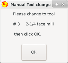
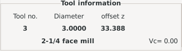
These pins are provided to use GMOCCAPY’s internal tool change dialog, similar to the one known from AXIS, but with several modifications. So you will not only get the message to change to tool number 3, but also the description of that tool like 7.5 mm 3 flute cutter. The information is taken from the tool table, so it is up to you what to display.
-
gmoccapy.toolchange-number (s32 IN) - The number of the tool to be changed
-
gmoccapy.toolchange-change (bit IN) - Indicates that a tool has to be changed
-
gmoccapy.toolchange-changed (bit OUT) - Indicates tool has been changed
-
gmoccapy.toolchange-confirm (bit IN) - Confirms tool change
Usually they are connected like this for a manual tool change:
net tool-change gmoccapy.toolchange-change <= iocontrol.0.tool-change
net tool-changed gmoccapy.toolchange-changed <= iocontrol.0.tool-changed
net tool-prep-number gmoccapy.toolchange-number <= iocontrol.0.tool-prep-number
net tool-prep-loop iocontrol.0.tool-prepare <= iocontrol.0.tool-prepared
|
Nota
|
Tenga cuidado, que estas conexiones deben hacerse en el archivo HAL postgui. |
These pins allow you to show the active tool offset values for X and Z in the tool information frame. You should know that they are only active after G43 has been sent.
-
gmoccapy.tooloffset-x (float IN)
-
gmoccapy.tooloffset-z (float IN)
|
Nota
|
The tooloffset-x line is not needed on a mill, and will not be displayed on a mill with trivial kinematics. |
Para mostrar los desplazamientos actuales, los pines tienen que estar conectados así en el archivo postgui HAL:
net tooloffset-x gmoccapy.tooloffset-x <= motion.tooloffset.x
net tooloffset-z gmoccapy.tooloffset-z <= motion.tooloffset.z
|
Importante
|
Tenga en cuenta que GMOCAPPY se encarga de actualizar los offsets, enviando un G43 después de cualquier cambio de herramienta, ¡pero no en modo automático! De tal manera que escribir un programa ¡te hace responsable de incluir un G43 después de cada cambio de herramienta! |
6. Auto Tool Measurement
GMOCCAPY offers an integrated auto tool measurement. To use this feature, you will need to do some additional settings and you may want to use the offered HAL pin to get values in your own NGC remap procedure.
|
Importante
|
Antes de comenzar la primera prueba, ¡no olvide ingresar altura y velocidades de la sonda en la página de configuración! Ver Página de configuración de herramienta de medición. |
También podría ser una buena idea echar un vistazo al video de la herramienta de medición: ver videos relacionados con la medición de herramientas.
Tool Measurement in GMOCCAPY is done a little bit different to many other GUIs. You should follow these steps:
-
Toque de su pieza en X e Y.
-
Mida la altura de su bloque desde la base donde está ubicado su interruptor de herramienta hasta la cara superior del bloque (incluyendo la mordaza etc.).
-
Presione el botón de altura del bloque e ingrese el valor medido.
-
Ir al modo automático e iniciar su programa.
Here is a small sketch:
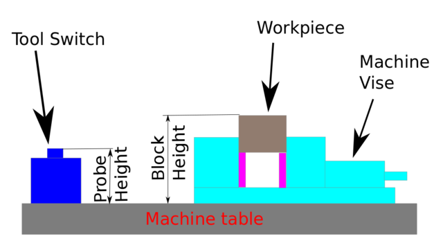
With the first given tool change the tool will be measured and the offset will be set automatically to fit the block height. The advantage of the GMOCCAPY way is, that you do not need a reference tool.
|
Nota
|
Your program must contain a tool change at the beginning! The tool will be measured, even it has been used before, so there is no danger, if the block height has changed. There are several videos showing the way to do that on YouTube. |
6.1. Provided Pins
GMOCCAPY offers five pins for tool measurement purposes. These pins are mostly used to be read from a G-code subroutine, so the code can react to different values.
-
gmoccapy.toolmeasurement (bit OUT) - Enable or not tool measurement
-
gmoccapy.blockheight (float OUT) - The measured value of the top face of the workpiece
-
gmoccapy.probeheight (float OUT) - The probe switch height
-
gmoccapy.searchvel (float OUT) - The velocity to search for the tool probe switch
-
gmoccapy.probevel (float OUT) - The velocity to probe tool length
6.2. INI File Modifications
Modifique su archivo INI para incluir las secciones siguientes.
[RS274NGC]
# sub que se llama cuando ocurre un error durante el cambio de herramienta, no se necesita en todas las configuraciones de máquina
ON_ABORT_COMMAND=O <on_abort> call

# The remap code
REMAP=M6  modalgroup=6 prolog=change_prolog ngc=change epilog=change_epilog
|
Nota
|
Make sure INI_VARS and HAL_PIN_VARS are not set to 0. They are set to 1 by default. |
The position of the tool sensor and the start position of the probing movement, all values are absolute coordinates, except MAXPROBE, which must be given in relative movement.
[TOOLSENSOR]
X = 10
Y = 10
Z = -20
MAXPROBE = -20
This is not named TOOL_CHANGE_POSITION on purpose - canon uses that name and will interfere otherwise. The position to move the machine before giving the change tool command. All values are in absolute coordinates.
[CHANGE_POSITION]
X = 10
Y = 10
Z = -2
The Python plug ins serves interpreter and task.
[PYTHON]
# The path to start a search for user modules
PATH_PREPEND = python
# The start point for all.
TOPLEVEL = python/toplevel.py
6.3. Needed Files
Primero cree un directorio "python" en su carpeta de configuración. Desde <su_directorio_linuxcnc-dev>/configs/sim/gmoccapy/python copie los archivos siguientes en la carpeta recién creada config_dir/python:
-
toplevel.py -
remap.py -
stdglue.py
From <your_linuxcnc-dev_directory>/configs/sim/gmoccapy/macros copy
-
on_abort.ngc -
change.ngc
al directorio especificado como SUBROUTINE_PATH, ver la Sección RS274NGC.
Open change.ngc with a editor and uncomment the following lines (49 and 50):
F #<_hal[gmoccapy.probevel]>
G38.2 Z-4
You may want to modify this file to fit more your needs.
6.4. Needed HAL Connections
Connect the tool probe in your HAL file like so:
net probe motion.probe-input <= <your_input_pin>
The line might look like this:
net probe motion.probe-input <= parport.0.pin-15-in
In your postgui.hal file add the following lines:
# The next lines are only needed if the pins had been connected before
unlinkp iocontrol.0.tool-change
unlinkp iocontrol.0.tool-changed
unlinkp iocontrol.0.tool-prep-number
unlinkp iocontrol.0.tool-prepared

# enlace al cambio de herramienta GMOCCAPY, para obtener la ventaja de la descripción en el cuadro de diálogo de cambio de herramienta
net tool-change gmoccapy.toolchange-change <= iocontrol.0.tool-change
net tool-changed gmoccapy.toolchange-changed => iocontrol.0.tool-changed
net tool-prep-number gmoccapy.toolchange-number <= iocontrol.0.tool-prep-number
net tool-prep-loop iocontrol.0.tool-prepare <= iocontrol.0.tool-prepared
7. The Settings Page
To enter the page you will have to click on
 and give an unlock code, which is 123 by default. If you want to change it at this time you will have to edit the hidden preference file, see the display section for details.
The page is separated in three main tabs:
7.1. Appearance
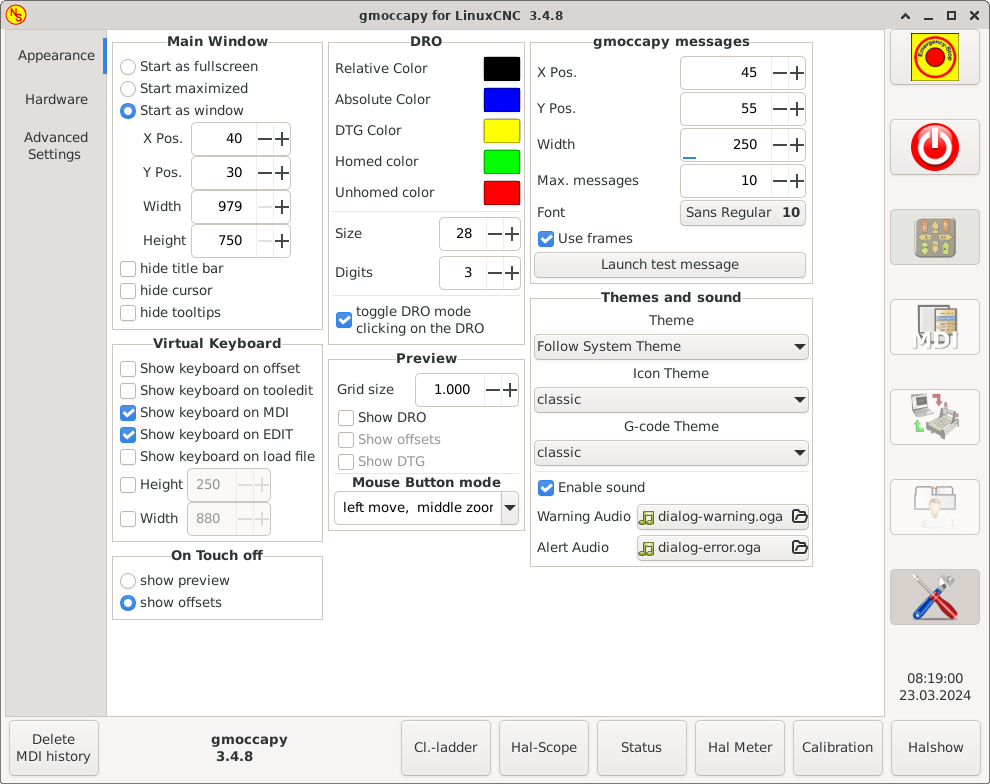
On this tab you will find the following options:
Here you can select how you wish the GUI to start. The main reason for this was the wish to get an easy way for the user to set the starting options without the need to touch code. You have three options:
-
Start as full screen
-
Start maximized
-
Iniciar como ventana - Si selecciona Iniciar como ventana, se activarán los cuadros para establecer la posición y el tamaño. Una vez establecidos, la GUI se iniciará cada vez en el lugar y con el tamaño seleccionado. Sin embargo, el usuario puede cambiar el tamaño y la posición con el ratón, pero eso influirá en la configuración.
-
hide title bar - Allows the title bar to be hidden. (default: title bar visible).
-
hide cursor - Does allow to hide the cursor, what is very useful if you use a touch screen.
-
hide tooltips - Hides the tool tips.
The checkboxes allow the user to select if he wants the on board keyboard to be shown immediately when entering the MDI Mode, the offset page, the tooledit widget or when open a program in the EDIT mode. The keyboard button on the bottom button list will not be affected by these settings, so you are able to show or hide the keyboard by pressing the button.
La configuración predeterminada es:
-
Show keyboard on offset = False
-
Show keyboard on tooledit = False
-
Show keyboard on MDI = True
-
Show keyboard on EDIT = True
-
Show keyboard on load file = False
|
Nota
|
If this section is not sensitive, you have not installed a virtual keyboard, supported ones are onboard and matchbox-keyboard. |
|
Nota
|
If the keyboard layout is not correct, i.e. clicking Y gives Z, than the layout has not been set properly, related to your locale settings. For onboard it can be solved with a small batch file with the following content: Las letras "de" son para Alemán, tendrá que configurar de acuerdo con su configuración regional (para español de España, es). Simplemente ejecute este archivo antes de iniciar LinuxCNC. También puede agregar un iniciador a su carpeta local. So that the layout is set automatically on starting. For matchbox-keyboard you will have to make your own layout, for a German layout ask in the forum. |

This gives the option whether to show the preview tab or the offset page tab when you enter the touch off mode by clicking the corresponding bottom button.
-
show preview
-
show offsets
Tiene la opción de seleccionar los colores de fondo de los diferentes estados del DRO. Por lo tanto, los usuarios que sufren de protanopia (debilidad roja/verde) pueden seleccionar los colores adecuados.
By default, the background colors are:
-
Relative Color = black
-
Absolute Color = blue
-
DTG Color = yellow
The foreground color of the DRO can be selected with:
-
Homed Color = green
-
Unhomed Color = red
|
Nota
|
Puede cambiar a través de los modos DRO (absoluto, relativo, distancia a recorrer) ¡haciendo clic en el DRO! Si haces clic en la letra del lado izquierdo del visualizador, una ventana emergente te permitirá establecer el valor de los ejes, lo que facilita el ajuste del valor, ya que no tendrás que pasar por el botón inferior de apagado. |
-
tamaño - Permite configurar el tamaño de la fuente DRO; el valor predeterminado es 28; si usa una pantalla más grande, es posible que desee aumentar el tamaño hasta 56. Si utiliza 4 ejes, el tamaño de fuente DRO será 3/4 del valor, debido a razones de espacio.
-
dígitos - Establece el número de dígitos del DRO de 1 a 5.
NotaImperial will show one digit more that metric. So if you are in imperial machine units and set the digit value to 1, you will get no digit at all in metric.
-
cambiar modo DRO - Si no está activo, un clic del ratón en el DRO no realizará ninguna acción.
De forma predeterminada, esta casilla de verificación está activa, por lo que cada clic en cualquier DRO cambiará la lectura DRO de real a relativa a DTG (distancia a recorrer).
Sin embargo, un clic en la letra del eje abrirá un diálogo emergente para asignar el valor del eje.
-
Grid Size - Sets the grid size of the preview window. Unfortunately the size has to be set in inches, even if your machine units are metric. We do hope to fix that in a future release.
NotaThe grid will not be shown in perspective view. -
Mostrar DRO - Mostrará el DRO también en el panel de vista previa. Se mostrará siempre en vista previa a tamaño completo.
-
Show DTG - Will show the DTG (direct distance to end point) in the preview pane if Show DRO is active. Otherwise only in full size preview.
-
Show Offsets - Will show the offsets in the preview pane when Show DRO is active. Otherwise only in full size preview.
-
Mouse Button Mode - This combobox allows you to select the button behavior of the mouse to rotate, move or zoom within the preview:
-
left rotate, middle move, right zoom
-
left zoom, middle move, right rotate
-
left move, middle rotate, right zoom
-
left zoom, middle rotate, right move
-
left move, middle zoom, right rotate
-
left rotate, middle zoom, right move
-
Predeterminado es mover a la izquierda, zoom medio, rotación a la derecha.
La rueda del ratón seguirá ampliando la vista previa en todos los modos.
|
Sugerencia
|
If you select an element in the preview, the selected element will be taken as rotation center point and in auto mode the corresponding code line will be highlighted. |
This will display small pop up windows displaying a message or error text, similar to the ones known from AXIS. You can delete a specific message by clicking on its close button. If you want to delete the last one, just hit the WINDOWS key on your keyboard, or delete all messages at once with Control + Space.
You are able to set some options:
-
X Pos - The position of the top left corner of the message in X counted in pixel from the top left corner of the screen.
-
Y Pos - The position of the top left corner of the message in Y counted in pixel from the top left corner of the screen.
-
Ancho - El ancho del cuadro de mensaje.
-
Max. messages - The maximum number of messages you want to see at once. If you set this to 10, the 11th message will delete the first one, so you will only see the last 10.
-
Fuente - La fuente y el tamaño que desea utilizar para mostrar los mensajes.
-
Use frames - If you activate the checkbox, each message will be displayed in a frame, so it is much easier to distinguish the messages. But you will need a little bit more space.
-
Launch test message-button - It will show a message, so you can see the changes of your settings without the need to generate an error.
Esto le permite al usuario seleccionar qué tema de escritorio aplicar y qué sonidos de error y mensajes deben reproducirse.
By default "Follow System Theme" is set.
It further allows to change the icon theme. Currently there are three themes available:
-
classic
-
material
-
material light
To create custom icon themes, see section Icon Theme for details.
7.2. Hardware
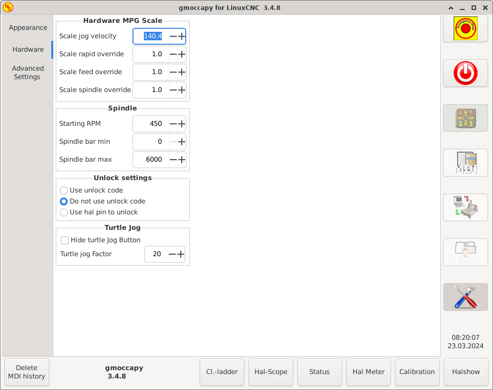
For the different HAL pins to connect MPG wheels to, you may select individual scales to be applied. The main reason for this was my own test to solve this through HAL connections, resulting in a very complex HAL file. Imagine a user having an MPG Wheel with 100 ppr and he wants to slow down the max. vel. from 14000 to 2000 mm/min, that needs 12000 pulses, resulting in 120 turns of the wheel! Or an other user having a MPG Wheel with 500 ipr and he wants to set the spindle override which has limits from 50 to 120 % so he goes from min to max within 70 pulses, meaning not even 1/4 turn.
By default all scales are set using the calculation:
(MAX - MIN)/100-
Starting RPM - Sets the rpm to be used if the spindle is started and no S value has been set.
NotaEste valor será predefinido de acuerdo con su configuración en [DISPLAY]DEFAULT_SPINDLE_SPEEDde su archivo INI. Si cambia la configuración en la página de configuración, ese valor será el predeterminado desde ese momento; su archivo INI no será modificado. -
Spindle bar min and Spindle bar max - Sets the limits of the spindle bar shown in the INFO frame on the main screen.
Los valores por defecto son:
MIN = 0
MAX = 6000NotaIt is no error giving wrong values. If you give a maximum of 2000 and your spindle makes 4000 RPM, only the bar level will be wrong on higher speeds than 2000 RPM.
There are three options to unlock the settings page:
-
Usar código de desbloqueo - El usuario debe dar un código para entrar.
-
No usar código de desbloqueo - No habrá verificación de seguridad.
-
Usar un pin para desbloquear - El pin de hardware debe estar alto para desbloquear la configuración, ver pin de desbloqueo hardware.
El valor predeterminado es usar el código de desbloqueo (predeterminado = * 123 *).
This settings will have influence on the jog velocities.
-
Hide turtle jog button - Will hide the button right of the jog velocity slider. If you hide this button, please take care that the "rabbit mode" is activated, otherwise you will not be able to jog faster than the turtle jog velocity, which is calculated using the turtle jog factor.
-
Factor de trote de tortuga - Establece la escala para el modo trote de tortuga (botón presionado mostrando la tortuga). Si le pone un factor de 20, la velocidad máxima de trote de tortuga será 1/20 de la velocidad máxima de la máquina.
|
Nota
|
This button can be controlled using the Turtle-Jog HAL Pin. |
7.3. Advanced Settings
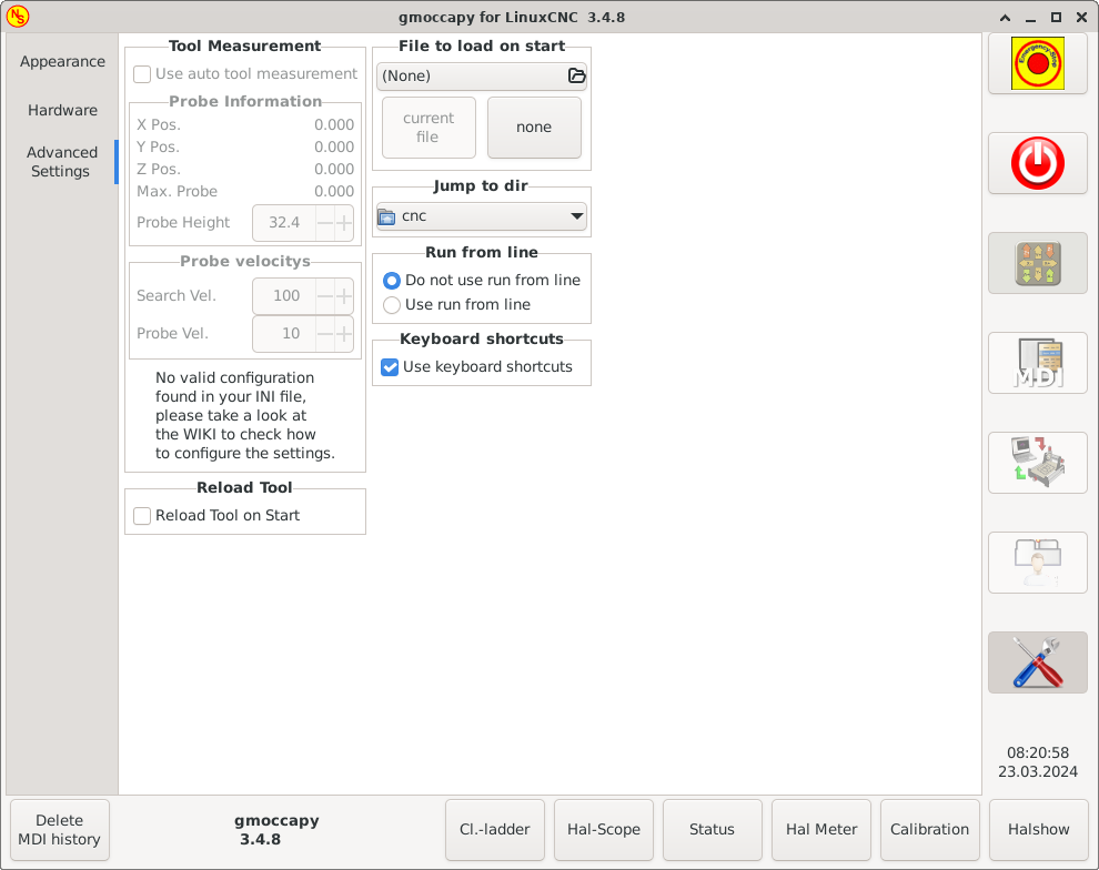
Please check Auto Tool Measurement
|
Nota
|
If this part is not sensitive, you do not have a valid INI file configuration to use tool measurement. |
-
Use auto tool measurement - If checked, after each tool change, a tool measurement will be done, the result will be stored in the tool table and a G43 will be executed after the change.
- Probe Information
-
Las información siguiente se toma de su archivo INI y se debe proporcionar en coordenadas absolutas:
-
X Pos. - La posición X del interruptor de herramienta.
-
Y Pos. - La posición Y del interruptor de herramienta.
-
Z Pos. - La posición Z del interruptor de la herramienta, iremos como movimiento rápido a esta coordenada.
-
Max. Probe - The distance to search for contact, an error will be launched, if no contact is given in this range. The distance has to be given in relative coordinates, beginning the move from Z Pos., so you have to give a negative value to go down!
-
Probe Height - The height of your probe switch, you can measure it. Just touch off the base where the probe switch is located and set that to zero. Then make a tool change and watch the tool_offset_z value, that is the height you must enter here.
-
- Probe velocities
-
-
Search Vel. - The velocity to search for the tool switch. After contact the tool will go up again and then goes towards the probe again with probe vel, so you will get better results.
-
Vel. Sonda - Es la velocidad para el segundo movimiento hacia el interruptor. Debe ser más lento para obtener mejores resultados. En modo sim, esto es comentado en macros/change.ngc, de lo contrario el usuario tendría que hacer clic dos veces en el botón de la sonda.
-
-
Reload Tool on Start - Loads the last tool on start after homing.
If checked, the tool in spindle will be saved on each change in the preference file, making it possible to reload the last mounted tool on start up. The tool will be loaded after all axes are homed, because before it is not allowed to execute MDI commands. If you use NO_FORCE_HOMING you can not use this feature, because the needed all_homed_signal will never be emitted.
Select the file you want to be loaded on start up. If a file is loaded, it can be set by pressing the current button. To avoid that any program is loaded at start up, just press the None button.
La pantalla de selección de archivos utilizará los filtros que haya configurado en el archivo INI. Si no hay filtros, solo verá los archivos NGC. La ruta se establecerá de acuerdo con la configuración de INI en [DISPLAY] PROGRAM_PREFIX.
You can set here the directory to jump to if you press the corresponding button in the file selection dialog.
You can allow or disallow the run from line. This will set the corresponding button insensitive (grayed out), so the user will not be able to use this option. The default is disable run from line.
|
Aviso
|
No se recomienda usar Ejecutar desde línea, ya que LinuxCNC no comprobará ninguna línea anterior en el código antes de la línea de inicio. Así, errores o choques son mas que probables. |
Algunos usuarios desean hacer jog usando los botones del teclado y hay otros que nunca lo permitirán. Así que todos pueden elegir si usarlos o no.
Los atajos de teclado están deshabilitados predeterminadamente. Pueden activarse con la casilla de verificación
-
Use keyboard shortcuts
|
Aviso
|
It is not recommended to use keyboard jogging, as it represents a serious risk for operator and machine. |
Por favor, tenga cuidado si usa un torno, ya que los atajos serán diferentes. Ver la Sección específica de torno.
8. Icon Theme
Icon themes are used to customize the look and feel of GMOCCAPY’s icons.
GMOCCAPY ships with three different icon themes:
-
classic - The classic GMOCCAPY icons.
-
material - A modern icon theme inspired by Google’s Material Icons that automatically adopts its coloring from the selected desktop theme.
-
material-light - Derived from material but optimized for light desktop themes.
The icon theme used in GMOCCAPY is a regular GTK icon theme that follows the freedestktop icon theme specification. Thus every valid GTK icon theme can be used as GMOCCAPY icon theme as long as it contains the required icons.
GMOCCAPY scans the following directories for icon themes:
-
linuxcnc/share/gmoccapy/icons
-
~/.icons
8.1. Custom Icon Theme
Creating a custom icon theme is pretty easy. All you need is a text editor and of course the desired icons as pixel or vector graphics. Details about how exactly an icon theme is built can be found at the Freedesktop Icon Theme Specification.
Start by creating an empty directory with the name of the icon theme. Place the directory in one of GMOCCAPY’s icon theme directories. Then we need a file called index.theme in the root folder of our icon theme which contains the required metadata for the theme. That’s a simple text file with at least the following sections:
-
[Icon Theme]
[Icon Theme] Name=YOUR_THEME_NAME Comment=A DESCRIPTION OF YOUR THEME Inherits=hicolor Directories=16x16/actions,24x24/actions,32x32/actions,48x48/actions,scalable/actions-
Name: The name of your icon theme.
-
Comment: A description of your icon theme.
-
Inherits: A icon theme can derive from another icon theme, the default is hicolor.
-
Directories: A comma separated list of all the directories of your icon theme.
Each directory usually contains all the icons of the theme in a specific size, for example 16x16/actions should contain all icons with the category "actions" in the size 16x16 pixels as pixel-graphics (e.g. png files). A special case is the directory called "scalable/actions", this contains scalable icons not tied to a specific size (e.g. svg files).
By supplying different sized versions of the icons, we can guarantee a nice looking icon if different sizes and we also have the ability to change the icon according to its size, for example a 64x64 px sized icon may contain more details than its 16x16 px version.
-
-
For each directory we also have to write a section in the index.theme file:
[16x16/actions] Size=16 Type=Fixed Context=Actions [scalable/actions] Size=48 Type=Scalable Context=Actions-
Size: Nominal icon size in this directory
-
Type: Fixed, Threshold or Scalable
-
Context: Intended "category" of icons
-
Basically that’s everything needed to create a custom icon theme.
8.2. Symbolic Icons
Symbolic icons are a special type of icon, usually a monochrome image. The special feature of symbolic icons is that the icons are automatically colored at runtime to match the desktop theme. That way, icon themes can be created that work well with dark and also light desktop themes (in fact, that’s not always the best option, that’s why a dedicated "material-light" theme exists).
To make use of the symbolic feature, a icon file has to have the suffix .symbolic.$ext (where $ext is the regular file extension like png) for example "power_on.symbolic.png".
With that name, GTK treats this image as symbolic icon and applies some recoloring when loading the icon. There are only four colors allowed to use:
| Color | Hex Code | Description |
|---|---|---|
black |
|
Primary color, gets changed to match the desktop themes primary color. |
red |
|
Success: this color indicates "success" (usually something green’ish). |
green |
|
Warning: this color indicates "warning" (usually something yellow/orange’ish). |
blue |
|
Error: this color indicates "error" (usually something red’ish). |
|
Sugerencia
|
Examples of symbolic icons can be found at linuxcnc/share/gmoccapy/icons/material. |
9. Lathe Specific Section
If in the INI file LATHE = 1 is given, the GUI will change its appearance to the special needs for a lathe. Mainly the Y axis will be hidden and the jog buttons will be arranged in a different order.
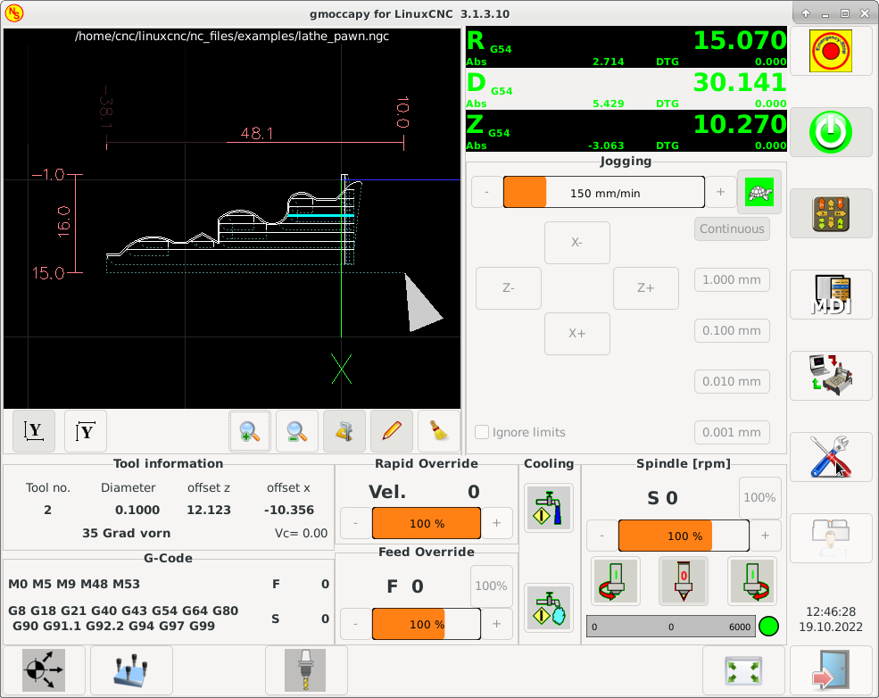
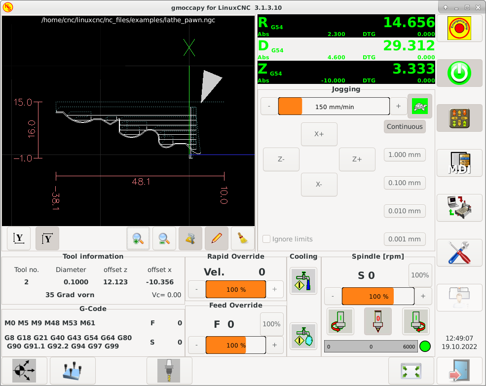
As you see the R DRO has a black background and the D DRO is gray. This will change according to the active G-code G7 or G8. The active mode is visible by the black background, meaning in the shown images G8 is active.
The next difference to the standard screen is the location of the jog buttons. X and Z have changed places and Y is gone. You will note that the X+ and X- buttons changes there places according to normal or back tool lathe.
Also the keyboard behavior will change:
Normal Lathe:
-
Arrow_Left or NumPad_Left - Jog Z minus
-
Arrow_Right or NumPad_Right - Jog Z plus
-
Arrow_up or NumPad_Up - Jog X minus
-
Arrow_Down or NumPad_Down - Jog X plus
Back Tool Lathe:
-
Arrow_Left or NumPad_Left - Jog Z minus
-
Arrow_Right or NumPad_Right - Jog Z plus
-
Arrow_up or NumPad_Up - Jog X plus
-
Arrow_Down or NumPad_Down - Jog X minus
The tool information frame will show not only the Z offset, but also the X offset and the tool table is showing all lathe relevant information.
10. Plasma Specific Section
Hay un muy buen WIKI, que en realidad está creciendo, mantenido por Marius. Vea página wiki de Plasma.
11. Videos on YouTube
Below is a series of videos that show GMOCCAPY in action. Unfortunately, these videos don’t show the latest version of GMOCCAPY, but the way to use it will still be the same as in the current version. I will update the videos as soon as possible.
11.1. Basic Usage
11.2. Simulated Jog Wheels
11.3. Settings Page
11.4. Simulated Hardware Button
German: https://youtu.be/DTqhY-MfzDE
English: https://youtu.be/ItVWJBK9WFA
11.5. User Tabs
11.6. Tool Measurement Videos
Auto Tool Measurement Simulation: https://youtu.be/rrkMw6rUFdk
Auto Tool Measurement Screen: https://youtu.be/Z2ULDj9dzvk
Auto Tool Measurement Machine: https://youtu.be/1arucCaDdX4
12. Known Problems
12.1. Strange numbers in the info area
If you get strange numbers in the info area of GMOCCAPY like:
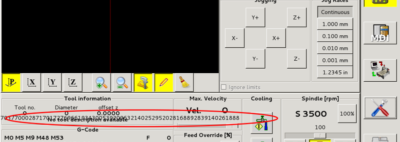
Ha creado su archivo de configuración con una versión anterior de StepConfWizard. Este ha hecho una entrada incorrecta en el archivo INI bajo [TRAJ]MAX_LINEAR_VELOCITY = xxx. Cambia esa entrada a MAX_VELOCITY = xxx.
12.2. Not ending macro
If you use a macro without movement, like this one:
 o<zeroxy> sub

G92.1
G92.2
G40

G10 L20 P0 X0 Y0

o<zeroxy> endsub
m2
GMOCCAPY will not see the end of the macro, because the interpreter needs to change its state to IDLE, but the macro does not even set the interpreter to a new state. To avoid that just add a G4 P0.1 line to get the needed signal. The correct macro would be:
 o<zeroxy> sub

G92.1
G92.2
G40

G10 L20 P0 X0 Y0

G4 P0.1

o<zeroxy> endsub
m2