1. Introducción
LinuxCNC is capable of controlling a wide range of machinery using many different hardware interfaces.
StepConf is a program that generates configuration files for LinuxCNC for a specific class of CNC machine: those that are controlled via a standard parallel port, and controlled by signals of type step & direction.
StepConf is installed when you install LinuxCNC and is in the CNC menu.
StepConf places a file in the linuxcnc/config directory to store the choices for each configuration you create. When you change something, you need to pick the file that matches your configuration name. The file extension is .stepconf.
The StepConf Wizard works best with at least 800 x 600 screen resolution.
2. Start Page
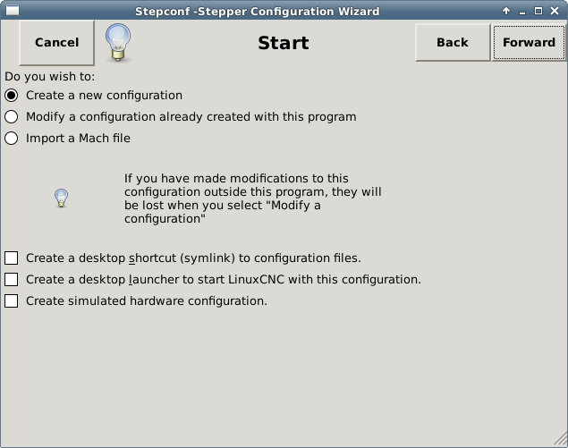
The three first radio buttons are self-explanatory:
-
Create New - Creates a fresh configuration.
-
Modificar una configuración ya creada… - Modifica una configuración existente. Después de seleccionar esta opción, aparecerá una pantalla de selección de archivo y usted deberá seleccionar el archivo con extensión .stepconf que desea modificar. Si usted realizó alguna modificación previa a los archivos principales .hal o .ini, estas modificaciones se perderán. Las modificaciones en los archivos custom.hal y custom_postgui.hal no serán cambiadas por el asistente Stepconf. El asistente Stepconf resaltará la ultima configuración que se construyó.
-
Import - Import a Mach configuration file and attempt to convert it to a LinuxCNC config file. After the import, you will go though the pages of StepConf to confirm/modify the entries. The original mach XML file will not be changed.
These next options will be recorded in a preference file for the next run of StepConf.
-
Create Desktop Shortcut - This will place a link on your desktop to the files.
-
Create Desktop Launcher - This will place a launcher on your desktop to start your application.
-
Crear Hardware Simulado - Permite crear una configuración para pruebas, incluso si no tiene el hardware real.
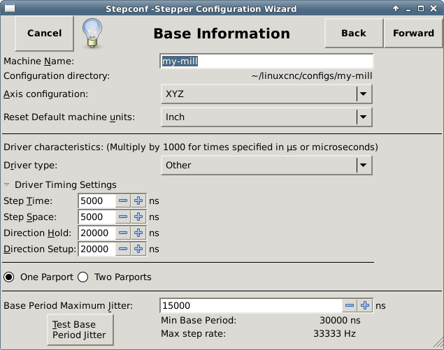
3. Basic Information
-
Crear Hardware Simulado - Permite crear una configuración para pruebas, incluso si no tiene el hardware real.
-
Machine Name - Choose a name for your machine. Use only uppercase letters, lowercase letters, digits, - and _.
-
Axis Configuration - Choose XYZ (Mill), XYZA (4-axis mill) or XZ (Lathe).
-
Machine Units - Choose Inch or mm. All subsequent entries will be in the chosen units. Changing this also changes the default values in the Axes section. If you change this after selecting values in any of the axes sections, they will be over-written by the default values of the selected units.
-
Driver Type - If you have one of the stepper drivers listed in the pull down box, choose it. Otherwise, select Other and find the timing values in your driver’s data sheet and enter them as nano seconds in the Driver Timing Settings. If the data sheet gives a value in microseconds, multiply by 1000. For example, enter 4.5 µs as 4500 ns.
A list of some popular drives, along with their timing values, is on the LinuxCNC.org Wiki under Stepper Drive Timing.
El acondicionamiento o aislamiento extra de señal, como cuando se usan optoacopladores y filtros RC en tarjetas breakboards, pueden imponer restricciones de tiempo por si mismos, además de las del controlador. Puede ser el caso que se requiera agregar tiempo extra a los valores de temporizacion para compensar los filtros o aislamientos.
The LinuxCNC Configuration Selector has configs for Sherline already configured. * Step Time - How long the step pulse is on in nano seconds. If your not sure about this setting a value of 20,000 will work with most drives. * Step Space - Minimum time between step pulses in nano seconds. If your not sure about this setting a value of 20,000 will work with most drives. * Direction Hold - How long the direction pin is held after a change of direction in nanoseconds. If your not sure about this setting a value of 20,000 will work with most drives. * Direction Setup - How long before a direction change after the last step pulse in nanoseconds. If your not sure about this setting a value of 20,000 will work with most drives. * One / Two Parport - Select how many parallel port are to be configured. * Base Period Maximum Jitter - Enter the result of the Latency Test here. To run a latency test press the Test Base Period Jitter button. See the Latency Test section for more details. * Max Step Rate - Stepconf calculará automáticamente la tasa maxima de pulsos de pasos basándose en las características del controlador del motor capturadas y en el resultado de la prueba de latencia. * Min Base Period - Stepconf calculará automáticamente el periodo base mínimo basándose en las características del controlador del motor capturadas y el resultado de la prueba de latencia.
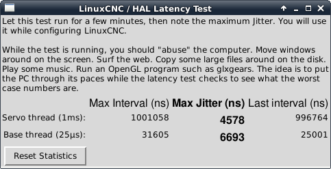
4. Latency Test
While the test is running, you should abuse the computer. Move windows around on the screen. Surf the web. Copy some large files around on the disk. Play some music. Run an OpenGL program such as glxgears. The idea is to put the PC through its paces while the latency test checks to see what the worst case numbers are. Run the test at least a few minutes. The longer you run the test the better it will be at catching events that might occur at less frequent intervals. This is a test for your computer only, so no hardware needs to be connected to run the test.
|
Aviso
|
Do not attempt run LinuxCNC while the latency test is running. |
La latencia es el tiempo que le tomara a una PC concreta detener lo que esta haciendo y responder a una solicitud externa. En este caso, la solicitud es el latido periódico que sirve como referencia de tiempo para la generación de los pulsos de paso. Cuanto menor sea la latencia, mas rápido se generarán los latidos, y los pulsos de paso serán mas rápidos y suaves.
Latency is far more important than CPU speed. The CPU isn’t the only factor in determining latency. Motherboards, video cards, USB ports, SMI issues, and a number of other things can hurt the latency.
The important numbers are the max jitter. In the example above 9075 nanoseconds (ns), or 9.075 microseconds (µs), is the highest jitter. Record this number, and enter it in the Base Period Maximum Jitter box.
Si el maximo retraso se encuentra entre 15-20 microsegundos o menor (15000-20000 nanosegundos), la computadora deberia dar muy buenos resultados con la generacion de pulsos de pasos. Si la latencia maxima esta entre 30-50 microsegundos, se pueden seguir obteniendo buenos resultados, pero la tasa maxima de generacion de pulsos puede ser un poco decepcionante, especialmente si se usan micropasos o un tornillo con un paso muy fino. Si los numeros son 100 µs o mas (100,000 nanosegundos), la PC no es una buena candidata para la generacion de pulsos de paso por software. Numeros superiores a 1 milisegundo (1,000,000 nanosegundos) significan que la PC no es una buena candidata para ejecutar LinuxCNC, sin importar si se usa generacion de pulsos de paso por software o no.
5. Parallel Port Setup
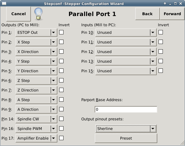
You may specify the address as a hexadecimal (often 0x378) or as linux’s default port number (probably 0)
For each pin, choose the signal which matches your parallel port pinout. Turn on the invert check box if the signal is inverted (0V for true/active, 5V for false/inactive).
-
Output pinout presets - Automatically set pins 2 through 9 according to the Sherline standard (Direction on pins 2, 4, 6, 8) or the Xylotex standard (Direction on pins 3, 5, 7, 9).
-
Inputs and Outputs - If the input or output is not used set the option to Unused.
-
External E-Stop - This can be selected from an input pin drop down box. A typical E-Stop chain uses all normally closed contacts.
-
Homing & Limit Switches - These can be selected from an input pin drop down box for most configurations.
-
Charge Pump - If your driver board requires a charge pump signal select Charge Pump from the drop down list for the output pin you wish to connect to your charge pump input. The charge pump output is connected to the base thread by StepConf. The charge pump output will be about 1/2 of the maximum step rate shown on the Basic Machine Configuration page.
-
Plasma Arc Voltage - If you require a Mesa THCAD to input a plasma arc voltage then select Plasma Arc Voltage from the list of output pins. This will enable a THCAD page during the setup procedure for the entry of the card parameters.
6. Parallel Port 2 Setup
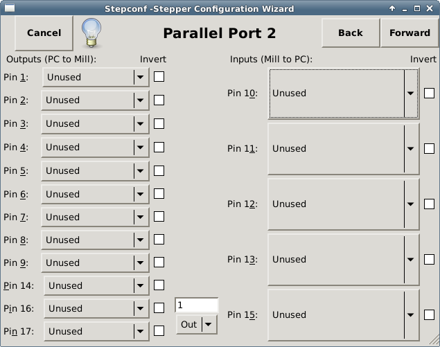
The second Parallel port (if selected) can be configured and It’s pins assigned on this page. No step and direction signals can be selected. You may select in or out to maximizes the number of input/output pins that are available. You may specify the address as a hexadecimal (often 0x378) or as linux’s default port number (probably 1).
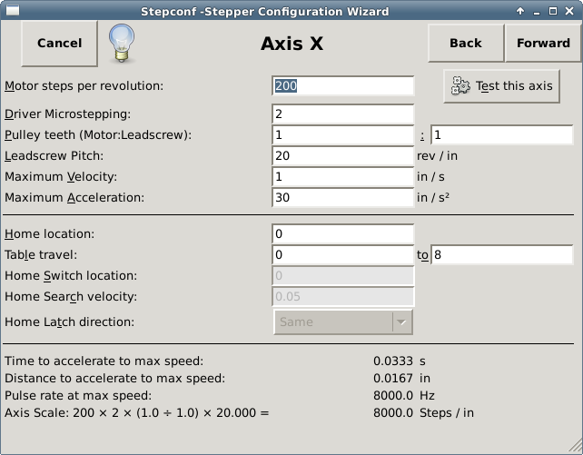
7. Axis Configuration
-
Motor Steps Per Revolution - The number of full steps per motor revolution. If you know how many degrees per step the motor is (e.g., 1.8 degree), then divide 360 by the degrees per step to find the number of steps per motor revolution.
-
Driver Microstepping - El número de micropasos producidos por el controlador. Entre 2 para semipasos.
-
Pulley Ratio - If your machine has pulleys between the motor and leadscrew, enter the ratio here. If not, enter 1:1.
-
Leadscrew Pitch - Enter the pitch of the leadscrew here. If you chose Inch units, enter the number of threads per inch. If you chose mm units, enter the number of millimeters per revolution (e.g., enter 2 for 2mm/rev). If the machine travels in the wrong direction, enter a negative number here instead of a positive number, or invert the direction pin for the axis.
-
Maximum Velocity - Entre la velocidad máxima del eje, en unidades por segundo.
-
Maximum Acceleration - The correct values for these items can only be determined through experimentation. See Finding Maximum Velocity to set the speed and Finding Maximum Acceleration to set the acceleration.
-
Posición Home - La posición a la que la maquina se moverá después de completar el procedimiento de inicio del eje. Para maquinas sin interruptores de posición home, esta es la posición a la cual el operador deberá mover la maquina antes de presionar el botón de inicio del eje (Home). Si se combinan interruptores home y de limite, se deberá mover la máquina fuera del interruptor para inicializar el eje o se recibirá un error de limite en el eje.
-
Table Travel - El rango de carrera que el código G no podrá sobrepasar. La posición de inicialización debe estar dentro del área de carrera y ser distinto a cualquiera de los valores de rango de carrera.
-
Home Switch Location - La ubicación en la cual el interruptor home se activa o desactiva, relativa al origen maquina. Este apartado y los dos siguientes solo aparecerán cuando se selecciona la existencia de interruptores home en la configuración de los pines del puerto paralelo. Si se combinan los interruptores de límite y de home, la ubicación del interruptor home no puede ser la misma que la posición home o se producirá un error de límite de articulación.
-
Home Search Velocity - Velocidad a usarse en la búsqueda de los interruptores home. Si el interruptor se encuentra cercano al limite de carrera del eje, esta velocidad debe ser seleccionada de tal forma que el eje tenga suficiente tiempo para desacelerar hasta detenerse antes de llegar al limite fisico de la carrera. Si el interruptor se encuentra cerrado en un rango corto de carrera, (en lugar de estar cerrado desde el punto de disparo hasta un final de carrera), la velocidad deberá ser seleccionada de tal forma que el eje pueda desacelerar hasta detenerse antes de que el interruptor se abra otra vez, y el procedimiento de homing deberá comenzarse siempre desde el mismo lado del interruptor. Si la máquina se mueve en la dirección contraria al inicio del homing, cambie el signo del parámetro Home Search Velocity.
-
Home Latch Direction - Seleccione Same para que el interruptor sea liberado y posteriormente la máquina se acerque a él a muy baja velocidad. La segunda vez que el interruptor se cierre, definirá la posicion home. Seleccione Opposite para realizar la inialización liberando lentamente el interruptor; cuando el interruptor se abra, se marcará la posición home.
-
Time to accelerate to max speed - Tiempo para alcanzar la velocidad máxima, calculado a partir de Max Acceleration y Max Velocity.
-
Distance to accelerate to max speed - Distancia para alcanzar máxima velocidad desde posición de parado.
-
Pulse rate at max speed - Este dato se calcula con base en los valores anteriores. El valor más grande de Pulse rate at max speed determina BASE_PERIOD. Valores por encima de 20000Hz pueden producir tiempos de respuesta muy bajos o incluso bloqueos (la tasa máxima varia entre computadoras)
-
Axis SCALE - El número que será usado en el archivo INI en la sección [SCALE]. Representa cuántos pasos se deben dar por unidad de usuario.
-
Test this axis - Esta opción abre una ventana para permitir probar cada eje. Puede ser utilizada después de llenar toda la información referente a este eje.
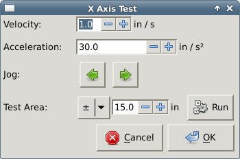
Test this axis is a basic tester that only outputs step and direction signals to try different values for acceleration and velocity.
|
Importante
|
In order to use test this axis you have to manually enable the axis if this is required. If your driver has a charge pump you will have to bypass it. Test this axis does not react to limit switch inputs. Use with caution. |
7.1. Finding Maximum Velocity
Begin with a low Acceleration
(for example, 2 inches/s2 or 50 mm/s2) and the velocity you hope to attain. Using the buttons provided, jog the axis to near the center of travel. Take care because with a low acceleration value, it can take a surprising distance for the axis to decelerate to a stop.
After gauging the amount of travel available, enter a safe distance in Test Area, keeping in mind that after a stall the motor may next start to move in an unexpected direction. Then click Run. The machine will begin to move back and forth along this axis. In this test, it is important that the combination of Acceleration and Test Area allow the machine to reach the selected Velocity and cruise for at least a short distance — the more distance, the better this test is. The formula d = 0.5 * v * v/a
gives the minimum distance required to reach the specified velocity with the given acceleration. If it is convenient and safe to do so, push the table against the direction of motion to simulate cutting forces. If the machine stalls, reduce the speed and start the test again.
If the machine did not obviously stall, click the Run button off. The axis now returns to the position where it started. If the position is incorrect, then the axis stalled or lost steps during the test. Reduce Velocity and start the test again.
If the machine doesn’t move, stalls, or loses steps, no matter how low you turn Velocity, verify the following:
-
Correct step waveform timings
-
Correct pinout, including Invert on step pins
-
Correct, well-shielded cabling
-
Physical problems with the motor, motor coupling, leadscrew, etc.
Once you have found a speed at which the axis does not stall or lose steps during this testing procedure, reduce it by 10% and use that as the axis Maximum Velocity.
7.2. Finding Maximum Acceleration
With the Maximum Velocity you found in the previous step, enter the acceleration value to test. Using the same procedure as above, adjust the Acceleration value up or down as necessary. In this test, it is important that the combination of Acceleration and Test Area allow the machine to reach the selected Velocity. Once you have found a value at which the axis does not stall or lose steps during this testing procedure, reduce it by 10% and use that as the axis Maximum Acceleration.
8. Spindle Configuration
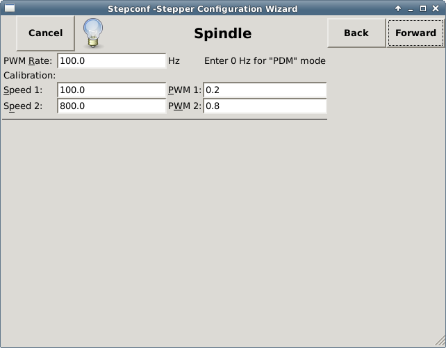
This page only appears when Spindle PWM is chosen in the Parallel Port Pinout page for one of the outputs.
8.1. Spindle Speed Control
If Spindle PWM appears on the pinout, the following information should be entered:
-
PWM Rate - The carrier frequency of the PWM signal to the spindle. Enter 0 for PDM mode, which is useful for generating an analog control voltage. Refer to the documentation for your spindle controller for the appropriate value.
-
Speed 1 and 2, PWM 1 and 2 - The generated configuration file uses a simple linear relationship to determine the PWM value for a given RPM value. If the values are not known, they can be determined. For more information see Determining Spindle Calibration.
8.2. Spindle-synchronized motion
When the appropriate signals from a spindle encoder are connected to LinuxCNC via HAL, LinuxCNC supports lathe threading. These signals are:
-
Spindle Index - Is a pulse that occurs once per revolution of the spindle.
-
Spindle Phase A - This is a pulse that occurs in multiple equally-spaced locations as the spindle turns.
-
Spindle Phase B (optional) - This is a second pulse that occurs, but with an offset from Spindle Phase A. The advantages to using both A and B are direction sensing, increased noise immunity, and increased resolution.
If Spindle Phase A and Spindle Index appear on the pinout, the following information should be entered:
-
Use Spindle-At-Speed - With encoder feedback one can choose to have LinuxCNC wait for the spindle to reach the commanded speed before feed moves. Select this option and set the close enough scale.
-
Speed Display Filter Gain - Setting for adjusting the stability of the visual spindle speed display.
-
Cycles per revolution - The number of cycles of the Spindle A signal during one revolution of the spindle. This option is only enabled when an input has been set to Spindle Phase A
-
Maximum speed in thread - The maximum spindle speed used in threading. For a high spindle RPM or a spindle encoder with high resolution, a low value of BASE_PERIOD is required.
8.3. Determining Spindle Calibration
Enter the following values in the Spindle Configuration page:
Speed 1: |
0 |
PWM 1: |
0 |
Speed 2: |
1000 |
PWM 2: |
1 |
Finish the remaining steps of the configuration process, then launch LinuxCNC with your configuration. Turn the machine on and select the MDI tab. Start the spindle turning by entering: M3 S100. Change the spindle speed by entering a different S-number: S800. Valid numbers (at this point) range from 1 to 1000.
For two different S-numbers, measure the actual spindle speed in RPM. Record the S-numbers and actual spindle speeds. Run StepConf again. For Speed enter the measured speed, and for PWM enter the S-number divided by 1000.
Because most spindle drivers are somewhat nonlinear in their response curves, it is best to:
-
Make sure the two calibration speeds are not too close together in RPM.
-
Make sure the two calibration speeds are in the range of speeds you will typically use while milling.
For instance, if your spindle will go from 0 RPM to 8000 RPM, but you generally use speeds from 400 RPM (10%) to 4000 RPM (100%), then find the PWM values that give 1600 RPM (40%) and 2800 RPM (70%).
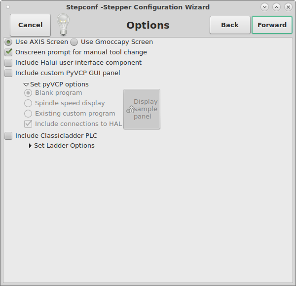
9. Options
-
Include Halui - This will add the Halui user interface component. See the HALUI Chapter for more information on.
-
Include PyVCP - This option adds the PyVCP panel base file or a sample file to work on. See the PyVCP Chapter for more information.
-
Include ClassicLadder PLC - This option will add the ClassicLadder PLC (Programmable Logic Controller). See the ClassicLadder Chapter for more information.
-
Onscreen Prompt For Tool Change - If this box is checked, LinuxCNC will pause and prompt you to change the tool when M6 is encountered. This feature is usually only useful if you have presettable tools.
10. Complete Machine Configuration
Click Apply to write the configuration files. Later, you can re-run this program and tweak the settings you entered before.
11. Axis Travels and Homes
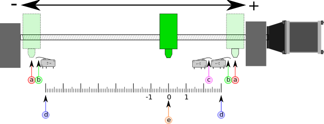
For each axis, there is a limited range of travel. The physical end of travel is called the hard stop.
|
Aviso
|
If a mechanical hard stop were to be exceeded, the screw or the machine frame would be damaged! |
Before the hard stop there is a limit switch. If the limit switch is encountered during normal operation, LinuxCNC shuts down the motor amplifier. The distance between the hard stop and limit switch must be long enough to allow an unpowered motor to coast to a stop.
Before the limit switch there is a soft limit. This is a limit enforced in software after homing. If a MDI command or G-code program would pass the soft limit, it is not executed. If a jog would pass the soft limit, it is terminated at the soft limit.
The home switch can be placed anywhere within the travel (between hard stops). As long as external hardware does not deactivate the motor amplifiers when the limit switch is reached, one of the limit switches can be used as a home switch.
The zero position is the location on the axis that is 0 in the machine coordinate system. Usually the zero position will be within the soft limits. On lathes, constant surface speed mode requires that machine X=0 correspond to the center of spindle rotation when no tool offset is in effect.
The home position is the location within travel that the axis will be moved to at the end of the homing sequence. This value must be within the soft limits. In particular, the home position should never be exactly equal to a soft limit.
11.1. Operating without Limit Switches
A machine can be operated without limit switches. In this case, only the soft limits stop the machine from reaching the hard stop. Soft limits only operate after the machine has been homed.
11.2. Operating without Home Switches
A machine can be operated without home switches. If the machine has limit switches, but no home switches, it is best to use a limit switch as the home switch (e.g., choose Minimum Limit + Home X in the pinout). If the machine has no switches at all, or the limit switches cannot be used as home switches for another reason, then the machine must be homed by eye or by using match marks. Homing by eye is not as repeatable as homing to switches, but it still allows the soft limits to be useful.
11.3. Home and Limit Switch wiring options
The ideal wiring for external switches would be one input per switch. However, the PC parallel port only offers a total of 5 inputs, while there are as many as 9 switches on a 3-axis machine. Instead, multiple switches are wired together in various ways so that a smaller number of inputs are required.
The figures below show the general idea of wiring multiple switches to a single input pin. In each case, when one switch is actuated, the value seen on INPUT goes from logic HIGH to LOW. However, LinuxCNC expects a TRUE value when a switch is closed, so the corresponding Invert box must be checked on the pinout configuration page. The pull up resistor show in the diagrams pulls the input high until the connection to ground is made and then the input goes low. Otherwise the input might float between on and off when the circuit is open. Typically for a parallel port you might use 47 kΩ;.


The following combinations of switches are permitted in StepConf:
-
Combine home switches for all axes
-
Combine limit switches for all axes
-
Combine both limit switches for one axis
-
Combine both limit switches and the home switch for one axis
-
Combine one limit switch and the home switch for one axis
The last two combinations are also appropriate when the type contact + home is used.